Preparation
Basic equipment
Here is a small list of the things I use to solder circuit boards:
Soldering station
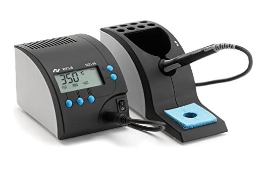
I use a somewhat higher quality soldering station from Ersa and am very satisfied. Mainly I use the fine soldering tip with 0,8mm diameter.![]()
PCB holder
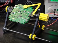
You can printed by yourself from the 3D printer.
Thingiverse
Solder

I only solder with leaded solder, I find it much easier than with lead-free solder. But I also don’t want to exclude that I am simply too stupid 😅. I linked what I bought.![]()
Tweezers
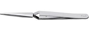
In my opinion a must have. With this the components can be held in place very easily. You fix the component and then turn the board around and you can easily solder the component firmly. It comes in different versions and lengths.![]()
![]()
![]()
Desoldering pump
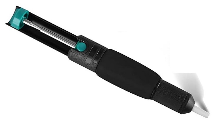
In case pads bond or too much solder is applied. For me such a cheap one up to €5 is perfectly sufficient.![]()
![]()
![]()
Side cutters / cable cutters
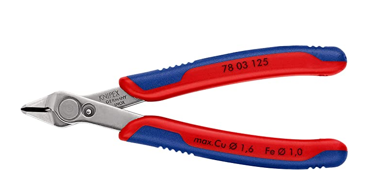
I guess I don’t have to explain the function 🙂![]()
![]()
Foreword
In order to always get good access to the components, I can only recommend to work from the lowest to the largest components. You should pay special attention to soldering cleanly and only put solder on the pads provided. If there is too much solder on one pad, or if two pads are connected, you can use a small desolder pumps to remove the excess solder.
It is also advisable to prepare all the necessary components and to make sure each time that the right component is soldered in the correct orientation. I don’t know how many times I installed male pin headers instead of female ones or vice versa. It is extremely difficult and annoying to remove them again. So it is better to check too much if everything is correct before soldering the component.
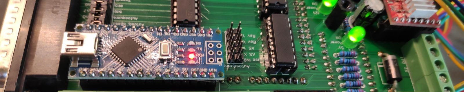
Arduino mega mini
I always solder them first before I start soldering the boards.
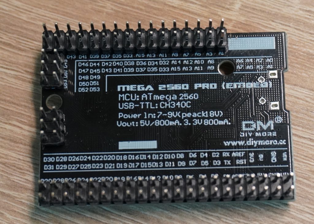
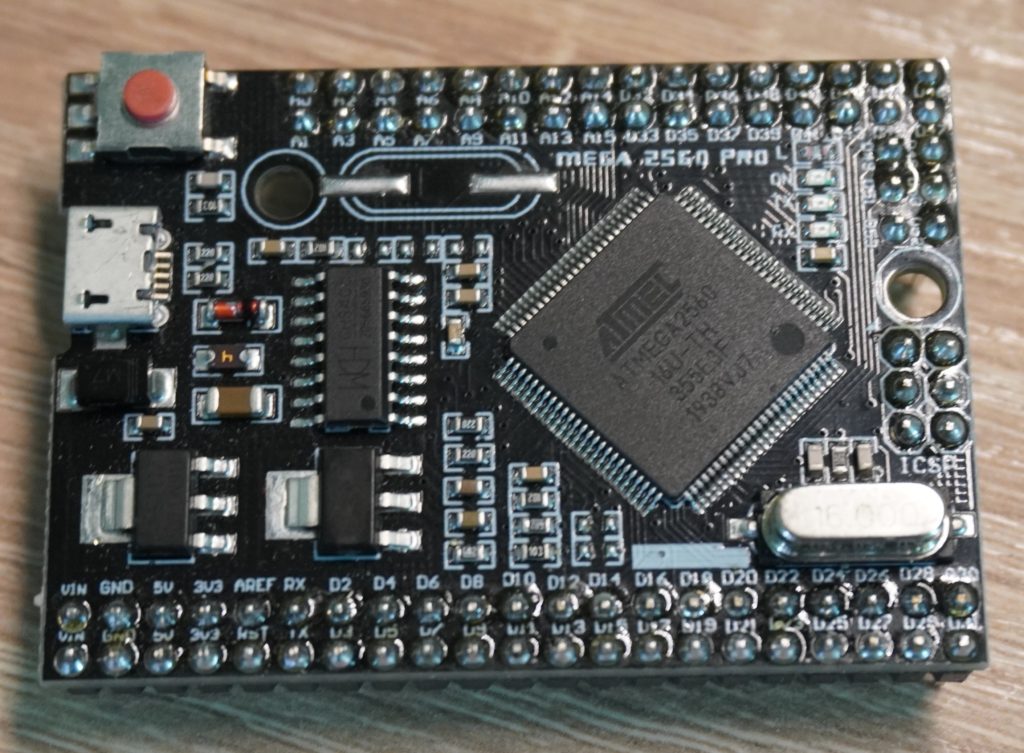
Contrary to many pictures you find online, I decided to let the pin headers point down. This way you can still see the LEDs and press the reset button.
Assembly
Video
The following video shows the complete soldering process for the OPEN-CNC-Shield The video has no sound or explanations and is intended to run alongside. The explanations for the individual steps can be found below. Please read everything carefully before soldering. It can easily happen that a component is soldered in the wrong way and then difficult to remove.
The whole process took me about 1.5 hours. The video plays in increased speed and takes about 30min. Just watch it, press stop in between and repeat the steps.
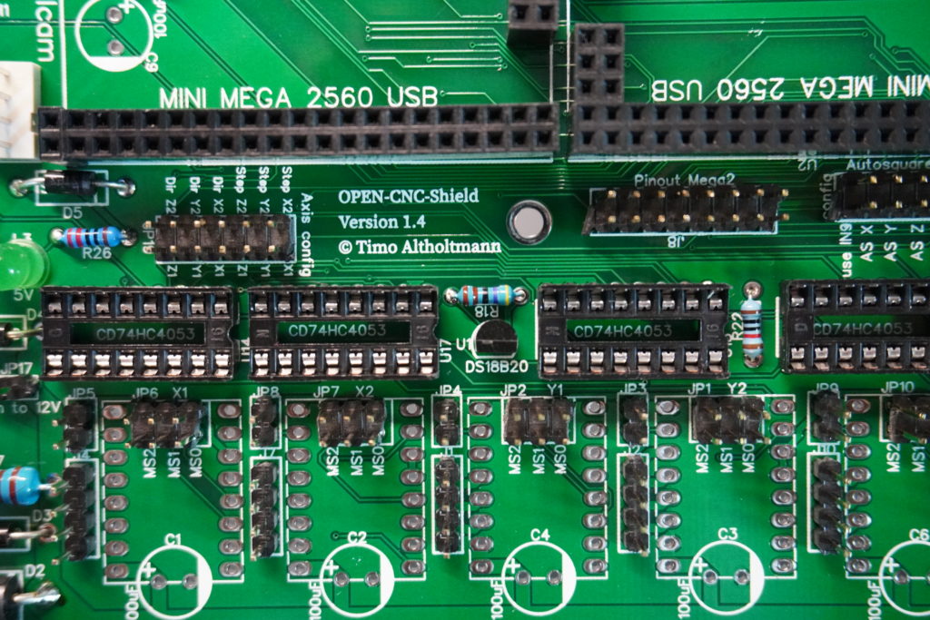
ICs
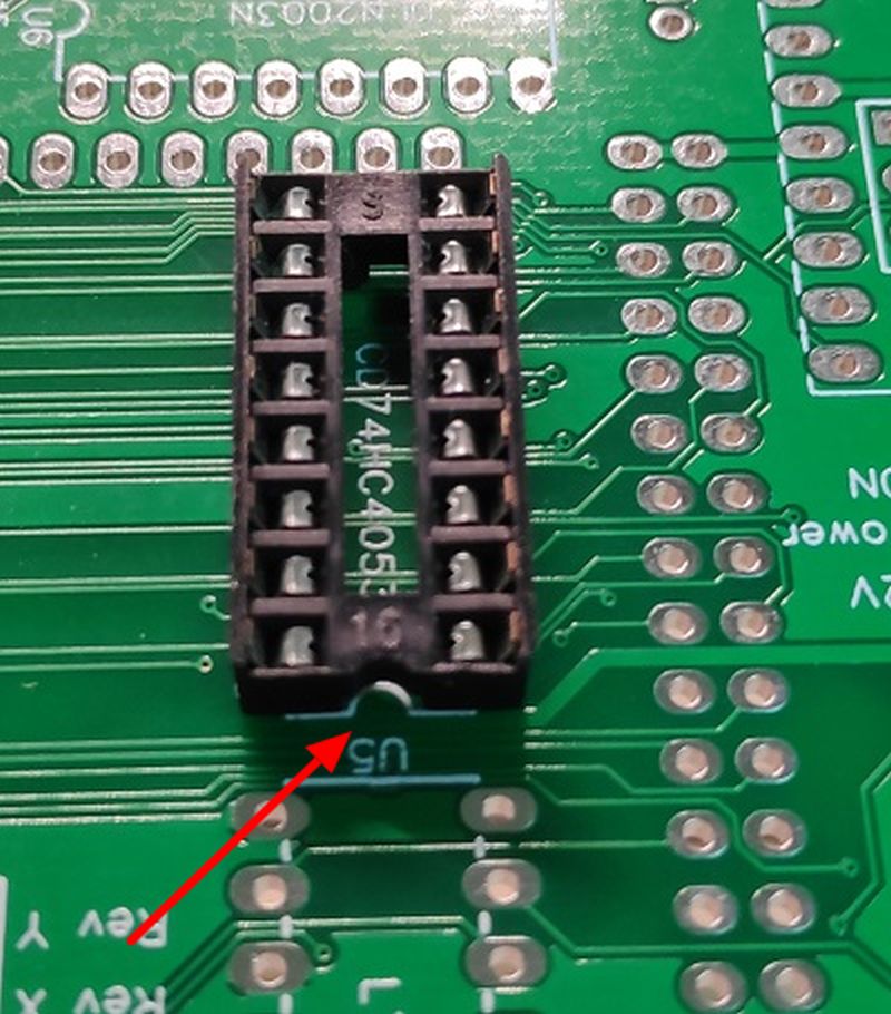
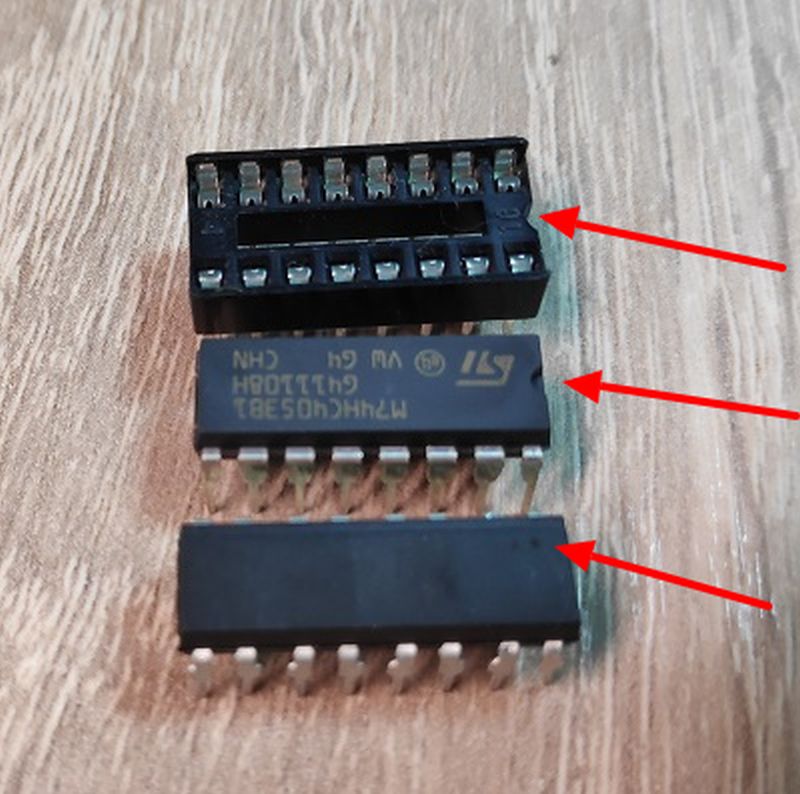
When soldering the IC sockets, it is important to pay attention to the right direction. The notches should be on top of each other as shown here in the picture. The ICs are also inserted in such a way that the notches lie on top of each other. Some ICs have a dot instead of a notch. In this case the point must lie over the notch of the socket.
You can also leave out the sockets and solder the ICs directly onto the board, but then it is very difficult to remove them, either because of a defect or because you accidentally put them in the wrong way.
Resistors
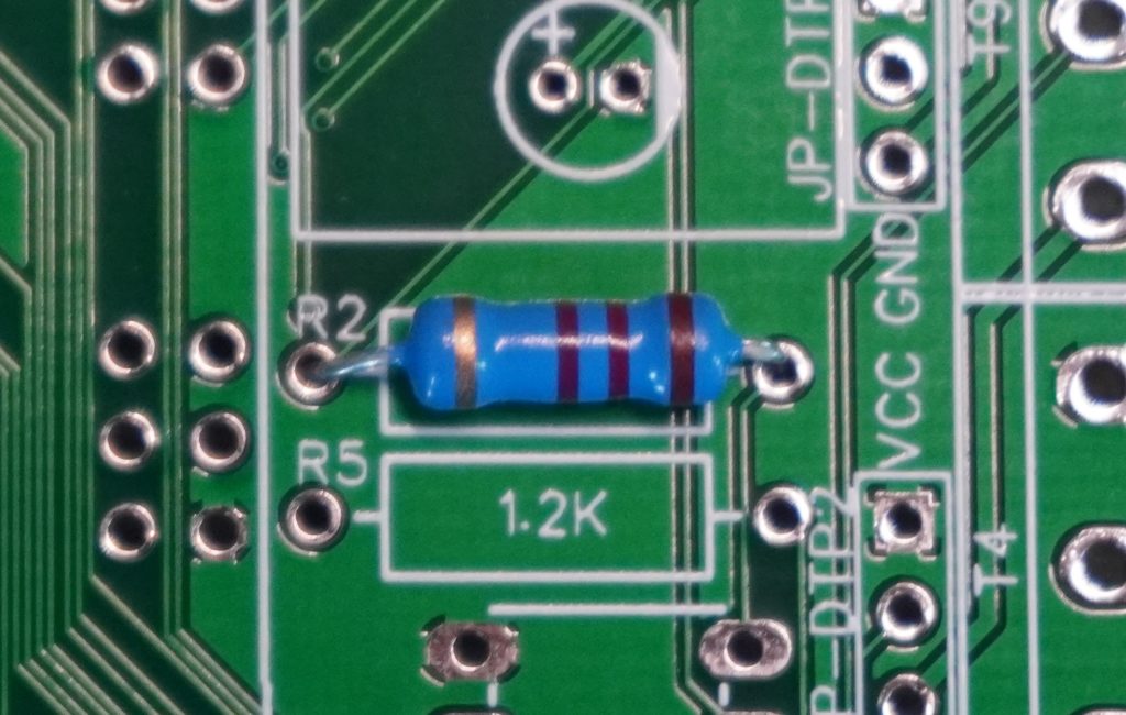
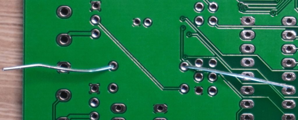
The orientation of the resistors does not matter. These can be put into the holes provided for it and then soldered. To prevent them from falling out again and again you can simply bend the legs on the other side. After soldering the legs are cut off.
If you want to determine the resistance value you can either use a measuring device or use the color codes to determine the value. There are also converters in the net, for example here: Calculator.
Diodes
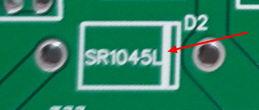
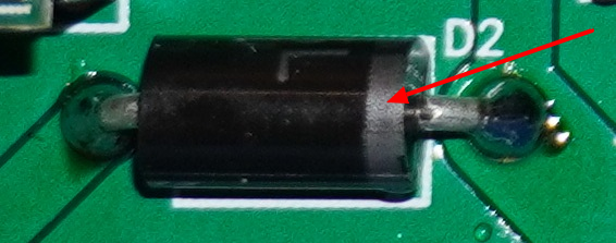
The alignment of the diodes is crucial. They only allow current to pass in one direction. You can orientate yourself by the marking on the board. The white line can be found on the board as well as on the diode and indicates the mounting direction.
Pin Header
The pin headers are simply cut to length with a side cutter and then soldered in.
Soldering Leds
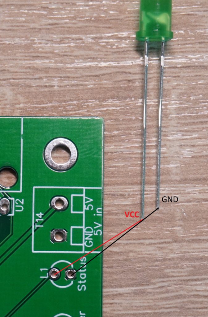
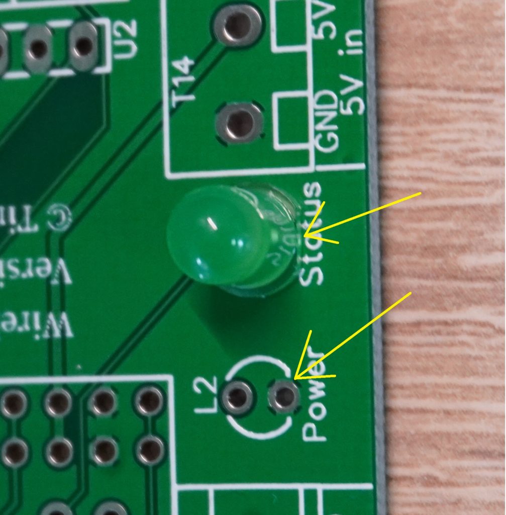
The LEDs can be soldered directly on the board as shown in the images. If you want to lead them out of a housing it is strongly recommended to solder pin headers instead. Then you can lead the LEDs later by cable from the board to the housing.
With LEDs, the alignment is crucial. The shorter leg of an LED is also here the minus pole. In addition, the LED is not quite round and has a small notch on the side. This also marks the minus pole and must correspond with the flattened side on the board.
Voltage converter
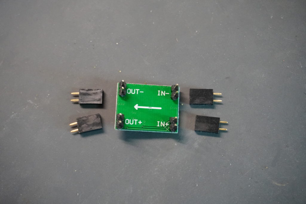
The voltage converters are provided with pin headers and then soldered in. So you can remove and adjust them again later. More about this in the Dokumentation.
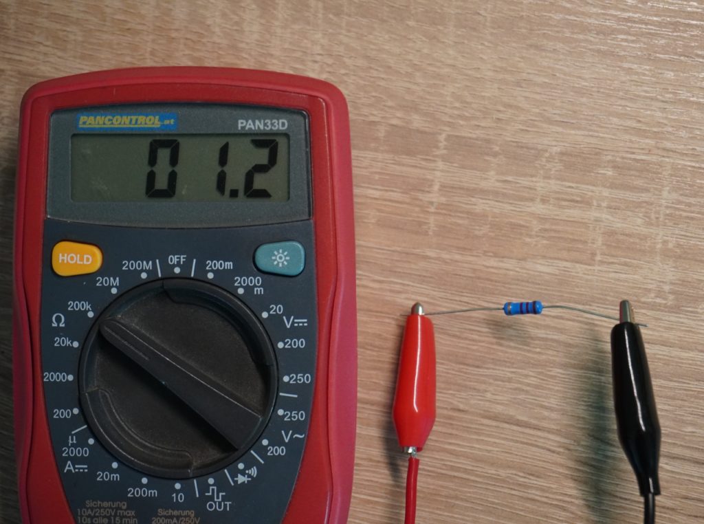
These must be set to the correct voltage before operation. Otherwise components on the board can be destroyed!
To adjust the voltage converters simply apply a voltage greater than 12V to the input pins (maximum 28V). And then measure the voltage at the outputs with a measuring device. With a small screwdriver the voltage can be varied with the screw. Please be careful here.
Arduino mini mega Header
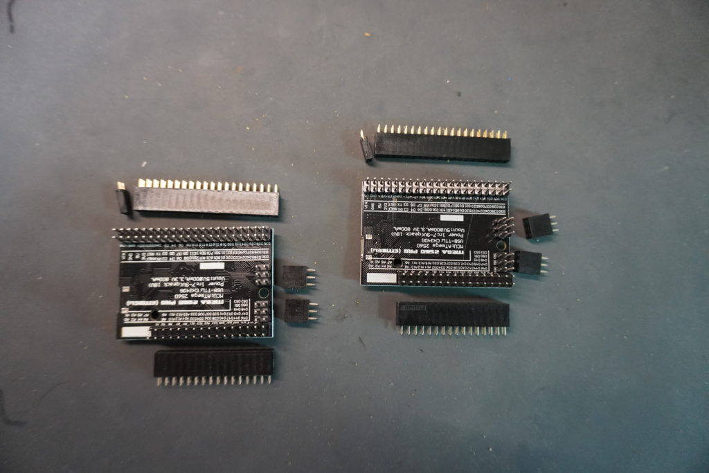
To mount the Arduino mini mega headers on the board, I simply plug them into the Arduino and then the whole component is plugged and soldered onto the board.
Capacitors
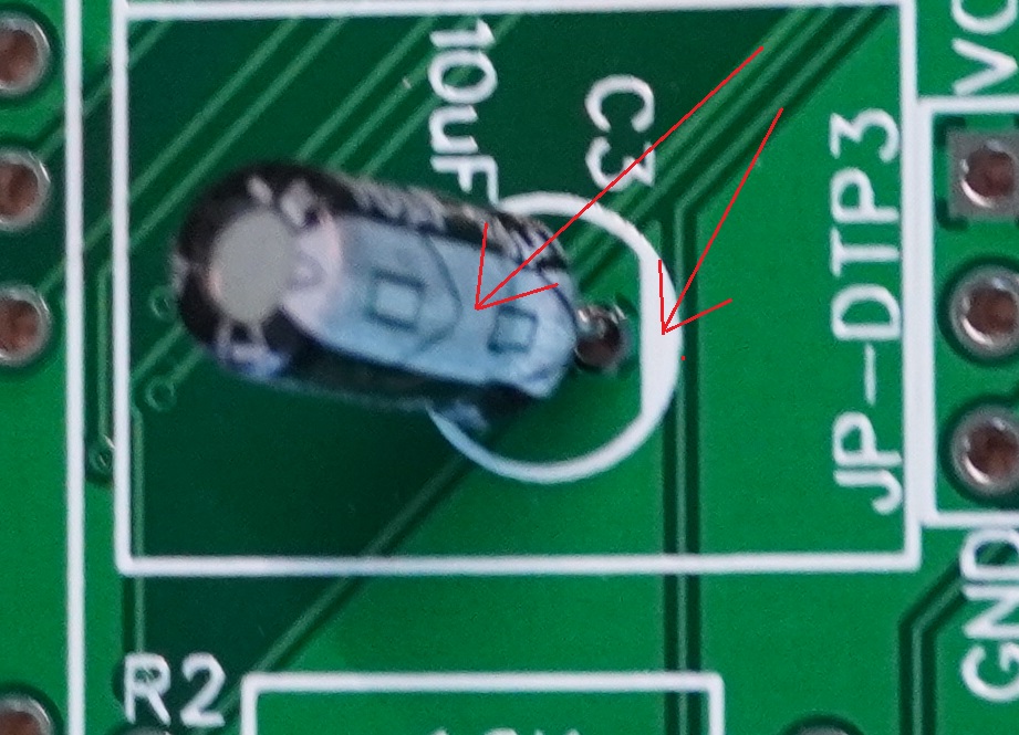
With capacitors it is very important to pay attention to the polarity. They usually have a white line on the side which marks the negative pole, this line must match the white mark on the board. In addition the leg of the negative leg is always the shorter one.
5k Ohm Potentiometer
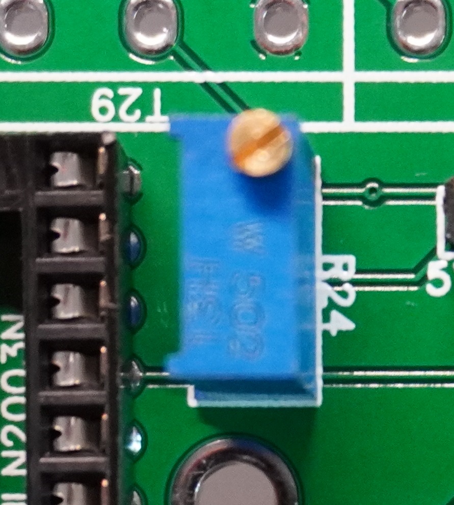
The orientation of this variable resistor is not important. For more information on the adjustment, please refer to the Calibrate Spindle section of the documentation.
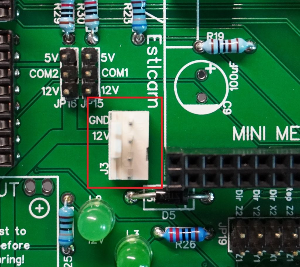
Fan plug
Please pay attention to the alignment here. Simply orientate on the image.
DS18B20
The temperature sensor must be soldered in carefully. Make sure that the soldering points do not connect.
Terminals
The screw terminals can often be plugged together and then soldered into one. Unfortunately, these are available with 5.08 mm spacing and with 5.0 mm spacing. On the PCB the distance is 5.08 mm so that all fit. Therefore it is possible that a long row of terminals does not fit in one piece and you might have to loosen them in one place.
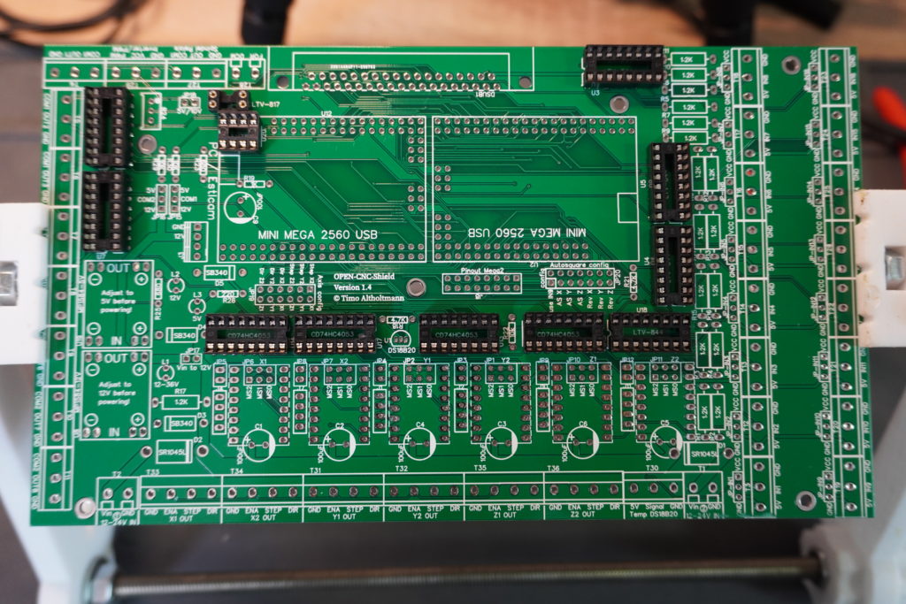
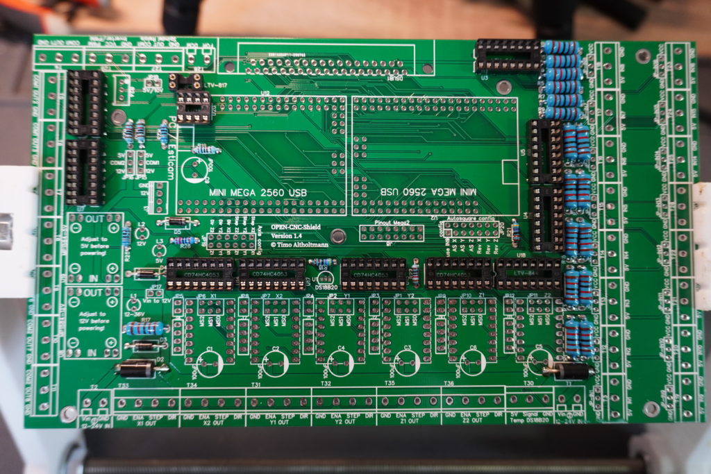
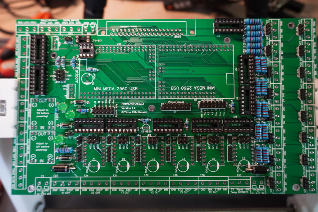
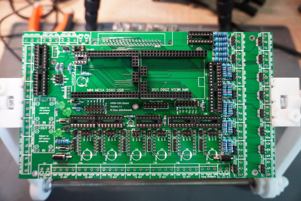
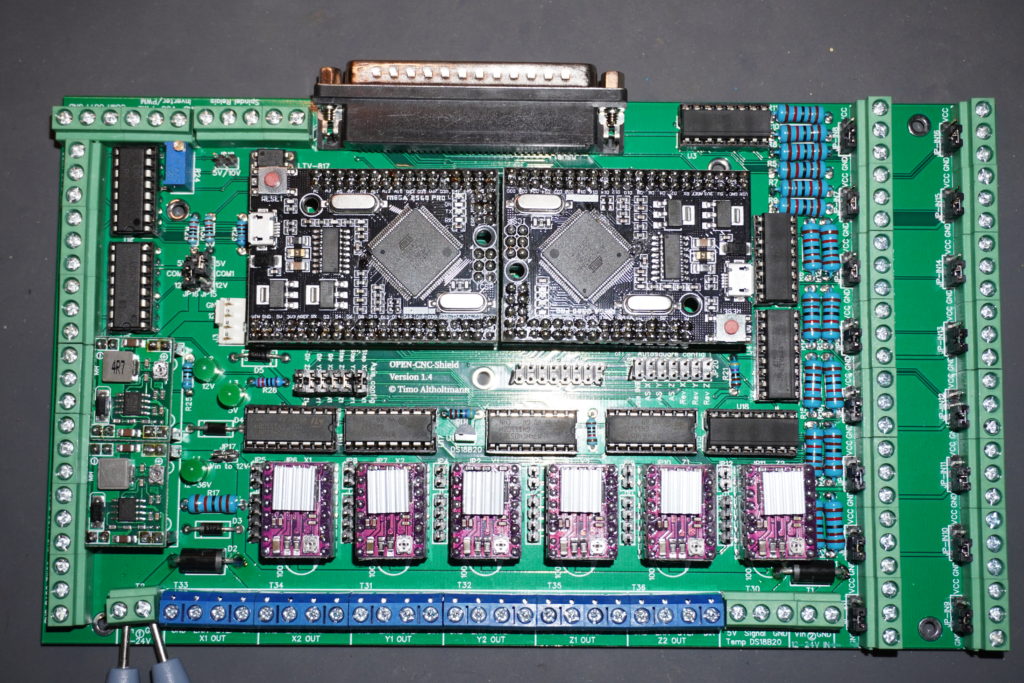
Ready assembled board
Testing
Check again that the voltage transformers have been set correctly. One with 5V and the other with 12V. After that you can apply current to the board and the LEDs should light up. From here you can continue with the OPEN-CNC-Shield documentation.