General
Description
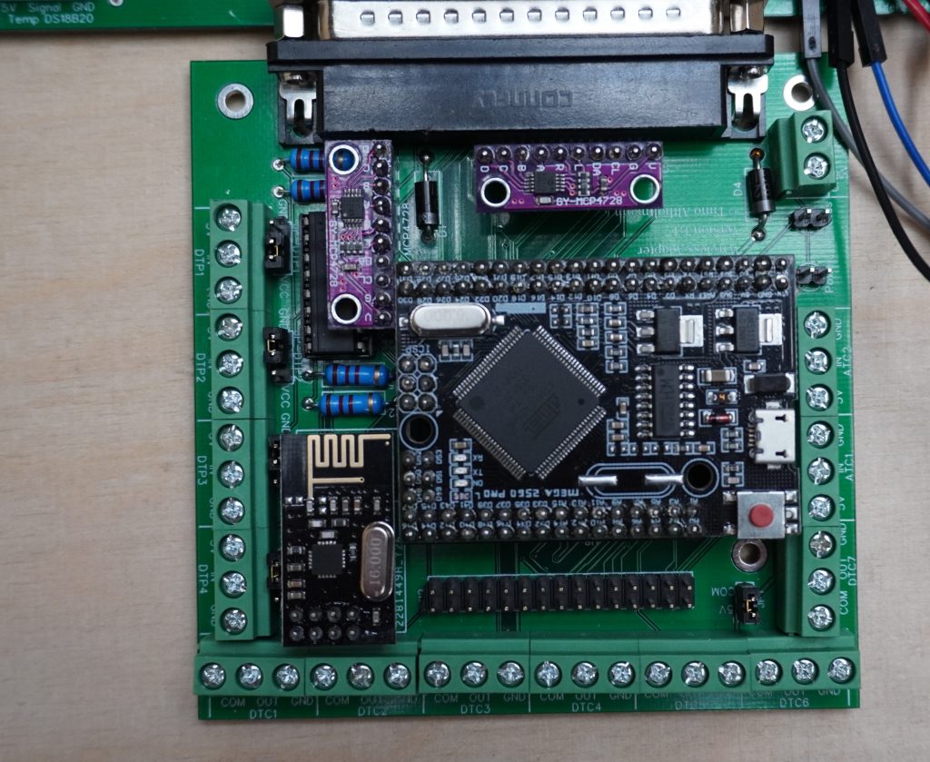
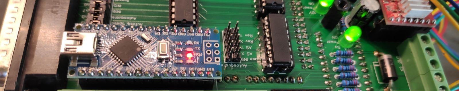
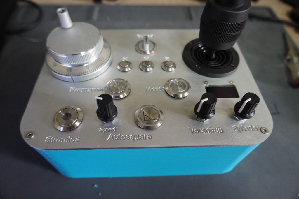
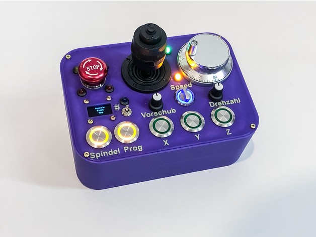
The wireless or radio solution for controlling a CNC milling machine is based on two boards, each of which is equipped with Arduino Mega. They communicate with each other via the NRF24L01 chip and exchange data. The design of the control panel can be freely configured. Additional elements can be added or removed as desired. The panel was developed for Estlcam. However, it is also possible to use other software. I am already working on an integration for LinuxCNC..
In the following video I introduce the Wireless Panel and show the different functions.
Functions
- Wireless communication via two Arduinos
- Connection via D-SUB 37 directly to the OPEN-CNC-Shield or the Tillboard Extension
- Other boards can be connected via a breakout board or with the Extension- Panel
- Connection of many control elements
- Hand wheel for moving the axes step by step
- Analog joystick for moving the axes
- Speed selection(Up to 6 steps in Estlcam configurable)
- Program Start/Stop
- Motor Start/Stop
- Control of the feed speed during the milling process
- Control of the spindle speed during the milling process
- Switch off the power of the motors(Enable- Connection of stepper drivers)
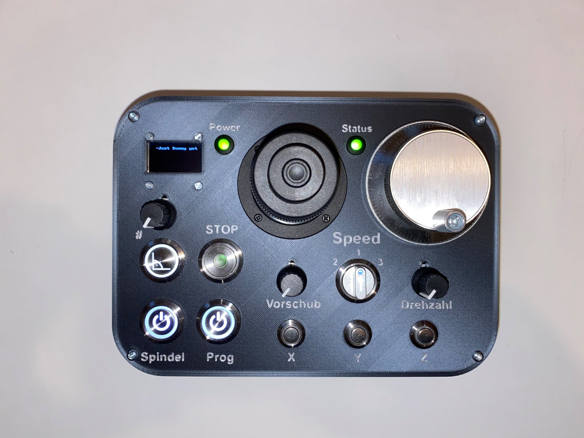
- individually configurable display, shows by default the autosquaring status of the axes, as well as the status of the temperature sensors (programming knowledge required if individual things are to be displayed)
- IN15 and IN16 of the controller can be switched
- Button and potentiometer for autosquaring
- Button for zeroing the axes (Here you can use e.g. the button on the 4-axis joystick)
- 7 digital channels from the control panel to the controller, called DTC1-7. Here you can connect e.g. switches or buttons which switch relays or similar
- 2 analog channels from the panel to the controller, ATC1 and ATC2. For example, a potentiometer can be connected to the control panel and the analog signal can be taken from the controller (e.g. control of the flux speed on ColdEnd)
- 4 digital channels from the controller to the control panel, DTP1-4. Here you could for example make a LED from the controller available on the panel.
- Digital channels can be triggered either with GND or with 5-24V, this is selectable by a jumper in each case
- Probably also usable with LinuxCNC directly via USB. For this there is an Arduino library called HAL2Arduino. But this is still in the test phase.
What do I need for which function?
Here is a list, which part you need for a function. Further down there is an overview of the components.
| Function | Component |
|---|---|
| Motor Start / Program Start | Push-button |
| Motor Stop / Program Stop | Push-button (But this is not required, since you can also simply press Start again) |
| OK(Zeroing) | Button (can be omitted, if you have a 4-axis joystick and you use the button of the joystick for this purpose) |
| Speed 1-6 | Rotary switch for 6 positions (I have only installed one for 3 positions – is perfectly sufficient for me) |
| selection X, Y, Z | One push button each. Here it makes sense to use a push button with LED, because the LED shows which axis is currently moved or selected. |
| Joystick | 3- or 4-axis analog joystick (for 4-axis the button can be used for OK/zeroing) |
| Hand wheel | Hand wheel with 4 connectors (A, B, VCC, GND). I find it superfluous, if the joystick is already installed. |
| Spindle speed | potentiometer with 5-10K ohms |
| Feed rate | potentiometer with 5-10K ohms |
| Autosquaring | Push-button to start Autosquaring |
| Autosquaring Speed | Potentiometer with 5-10K Ohm |
| Switch off power | Switch |
| Display | OLED Display |
Manufacturing / procuring circuit boards
If you don’t feel like getting the board and components yourself here is a small order form: https://forms.gle/eGtfc3Autmp8chfd6.
If you prefer to make the board yourself, this is also possible. The files are licensed under the Creative Commons CC BY-NC-SA 4.0 license and can be downloaded: Gitlab Repository
Required components
The following items are required for equipping the boards or commissioning the operating panel.
| Bauteil / Beschreibung | Link |
|---|---|
| Powerbank I have tested several Powerbanks. It was important to me that they can be charged at the same time and also supply the panel with power. It should also be small so that it can be easily placed in the housing. Therefore I decided to use the linked one. It has 5000mah, that should be enough power for many hours. There are certainly many other functional powerbanks. | |
Mega pro mini This is needed twice. Once for the Wireless Panel board and once for the Wireless Adapter board. There are several versions of these on the net. Make sure that a USB port is installed and that 3.3V is available in the pinout. | |
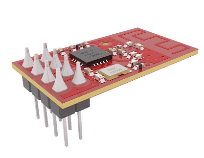
NRF24L01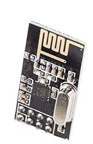 This radio module enables communication between the two Arduinos and is needed twice. | |
MCP4728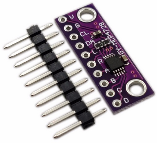 Since the Arduino can only output PWM signals and no real analog signals, this chip takes over the function. It is needed twice. |
Push button
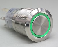
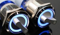
Available in different versions. They can be used with, or without LED. They are also available in many different diameters. I made good experience with 19 or 22 mm diameter. If you want smaller ones, they should have a raised head, otherwise you need very small fingers to operate them properly. LED buttons can be used either with or without series resistor. If it should be with LED, make sure that these can be operated with maximally 5V! 12V LEDs do not work, or shine weakly.![]()
![]()
![]()
![]()
Rotary switch
I would use one with 3 positions for the speed setting. That should be enough. With a little lighting it gets nicer, of course. With lighting always pay attention to max 5V. Otherwise, this should be a “latching” switch, meaning it stays in position and does not jump back automatically.![]()
Joystick
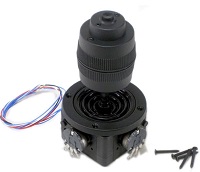
I have a 4 axis joystick with 10K ohms, but 5K ohms should also work.![]()
![]()
Handwheel
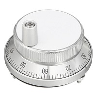
This is available with different diameters. I own the 60 mm version. Important is that it is 4-pin and designed for 5V.![]()
![]()
![]()
Potentiometer
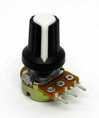
For the analog settings. Some with 5-10K Ohm should be used.
![]()
![]()
![]()
Display
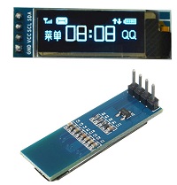
II use a 4 or 8 line OLED display with 128×32 or 128×64 pixels. Depending on which size you want to have. The display must be selected once in the Arduino code.![]()
![]()
![]()
Switch
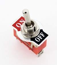
Here you basically have the free choice.![]()
![]()
![]()
Temperature sensors
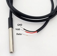
Here DS18B20 must be used, otherwise the Ardunino code must be adapted. Theoretically you can connect several of them in series, because they are connected with a 1-Wire bus. They are available in two versions, one as a naked component and one as a waterproof version. Depending on where you want to use it, you can order the appropriate version. To read and display multiple sensors, the Arduino program must also be edited.![]()
![]()
![]()
Housing
| Image | Description |
|---|---|
 | Housing for the 3D printer. Here the Powerbank linked under the components can be installed directly. I also uploaded the Fusion360 project, so you have the possibility to make adjustments and maybe choose a different layout for the cover. You can find it here on Thingiverse. |
 | A remake by Carsten Schröder. You can also find it on Thingiverse. |
 | A remake by Michael Kaufmann. It can be downloaded here as a zip file: LINK |
More about radio stability and range
The wireless adapter is located in a switch box, together with the control unit, the spindle FU etc. The distance to the panel is always about 2-3 meters.
Before the last software update I was constantly struggling with interruptions and dropouts. Starting with software version 2.1 the connection remains stable even if I am 10 meters away.
But if you still have problems, you can try the following:
These modules work much better than the NRF24L01+
| Bild | Link | |
|---|---|---|
 | With the E01-ML01D modules I made much better experiences regarding range and stability. They can easily be exchanged with the NRF24L01+ modules. | Aliexpress |
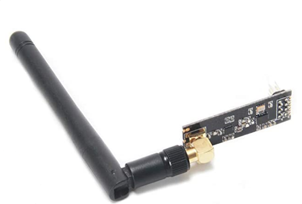 | If the modules above are still not enough, you can replace the radio module on the wireless adapter with one with an antenna – NRF24L01 PA LNA. (Please note that you can set “LNA_ANTENNA_CONNECTED” in the Arduino code to further amplify the signal). It should be enough to replace only the module on the adapter. | Amazon |
My recommended setup would be, if there is enough space: At the Wireless Adapter an NRF24L01 PA LNA with antenna and at the Wireless Panel an E01-ML01D. This way it runs smoothly and stable in my setup.
Assembly / soldering
There is an extra page for this → Wireless Control Assembly
Documentation
There is an extra page for this → Wireless Control documentation