Jumpers / Terminals / Connections
| Beschriftung | Funktion | Beschreibung |
|---|---|---|
| JP6, JP7, JP2, JP1, JP10, JP11 | Microsteps of the plug-on drivers | The microsteps of the plug-on drivers are set here. If external drivers are used, these jumpers can be left free. More about this under microsteps. |
| JP5, JP8, JP4, JP3, JP9, JP12 | Fault Jumper of the plug-on drivers | Must be set for A4988 driver. On DRV8825 the jumpers remain free. More about this under Fault Jumpers. |
| J4, J7, J1, J2, J10, J11 | Motor connection for plug-on drivers | This is where the motors are connected if the plug-on drivers are used. Scheme: 1A 1B 2A 2B. Are the motors turning the wrong way round just turn the plug once. More about this under connecting the motors. |
| JP19 | Configuration of the axes | The different axes can be connected with each other. If Estlcam is used as software, all jumpers should be set here. For more information see configuration of the axes. |
| JP20 | Autosquaring configuration | Here you can activate the autosquaring mode and set the direction of the motors during autosquaring. More about this under autosquaring configuration. |
| JP17 | Connects “Vin” to the 12V net | If the shield is operated with 12V, this jumper should be set. More about this under power supply. |
| JP15 and JP16 | Jumper for the voltage of the outputs | Here you can set the voltage for outputs 1-8. Each jumper sets the voltage for 4 outputs. More about this under outputs. |
| JP18 | Voltage of the speed control | If this jumper is set, the voltage of the analog output for the speed is between 0 and 5V. Otherwise it is between 0 and 10V. More about this under spindle control. |
Power supply
The OPEN-CNC-Shield can be operated with 12-24V. I recommend 24V.
If the Shield is supplied with 12V, it is possible that less than 12V will arrive in the 12V net, because the voltage converter causes a small voltage loss. For this case the jumper JP17 is provided. If this jumper is set, the input voltage will be transferred directly into the 12V net.
Attention, the jumper JP17 must not be set under any circumstances if more than 12V are applied to the terminal T2 (12-24V in). This can destroy various components on the board!
Required current
If no plug-on drivers are used, a 24V 5A power supply will be sufficient and offers reserves. The second 12-24V Vin is unnecessary in this case. Here is an example power supply: ![]()
If plug-on drivers are used, a stronger power supply should be used. In general you can expect about 2A per driver. For example, here is one with 24V and 15A, so all 6 drivers can be used without problems and there is still enough reserve: ![]()
The power supplies with high currents usually offer several connections. The second 12-24V Vin can be used for this. This is for safety reasons and should counteract the heat development at high currents.
Inputs
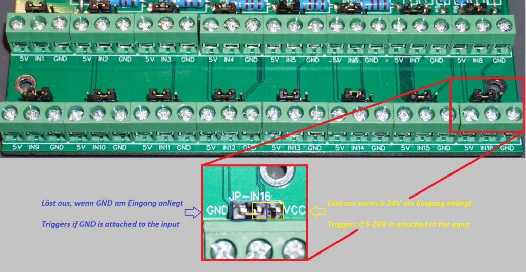
There are 16 inputs on the OPEN-CNC-Shield. These can be switched either with positive voltage of 5-24V or with GND. This is selectable by a jumper on the respective input. Each input has its own jumper.
If autosquaring is to be used, each motor needs its own end stop. More about this under Autosquaring.
Endstops
Normally closed / normally open
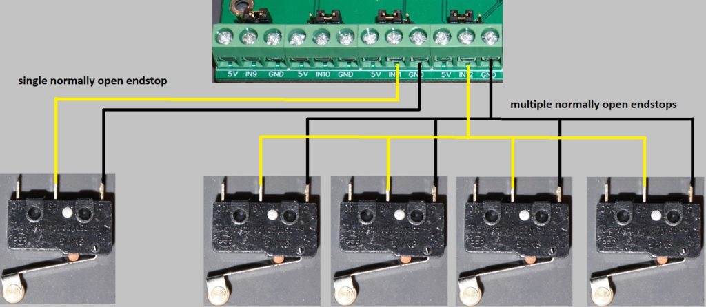
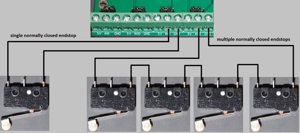
Either normally closed (normally closed / triggered) or normally open (normally open / not triggered) end stops can be connected. These can either be connected with several to one input or each end stop can be connected to its own input.
I would prefer a normally closed wiring, because also cable breaks can be detected directly. Inputs with normally closed sensors probably have to be inverted in the software.
Proximity sensors PNP or NPN
Both PNP sensors and NPN sensors can be connected. To do so, the appropriate jumper setting must be made at the input. These are also available as NC(normally closed) or NO(normally open) variant. See above for wiring.
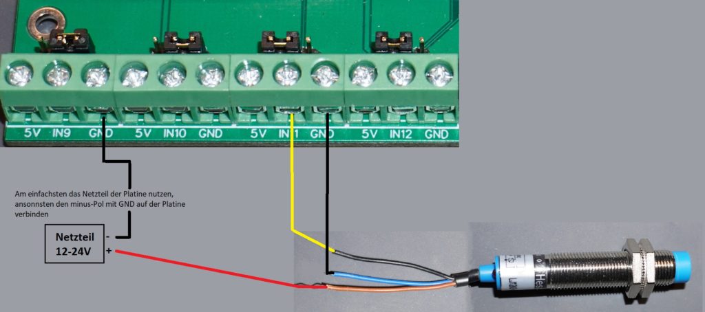
NPN NC Sensor: ![]()
![]()
Outputs
The OPEN-CNC-Shield offers 8 outputs, which can be switched in Estlcam as desired. There are two relay drivers installed. For each relay driver the voltage can be set by jumpers JP15 and JP16. OUT1-4 are connected to COM1 and are thus connected to a voltage by jumper JP15. Attention: COM1 is also used for the spindle relay, more about this under spindle control. OUT5-8 are connected to COM2 and are configured with jumper JP16.
For example, it is possible that outputs 1-4 work with 5V and outputs 5-8 with 12V. If you want to use a different voltage, you can leave the respective jumpers open and apply this voltage directly to COM1 or COM2. This voltage is then available at all COM connections of the same name, but must not exceed 50V.
A maximum of 500mA current may flow per output. Therefore always work with relays as soon as the limit is possibly exceeded. Also pay attention to the maximum currents of the nets. In the 5V and 12V networks a maximum of 3A for each net. The outputs are not the only consumers here – fans, Arduinos etc. also draw current!
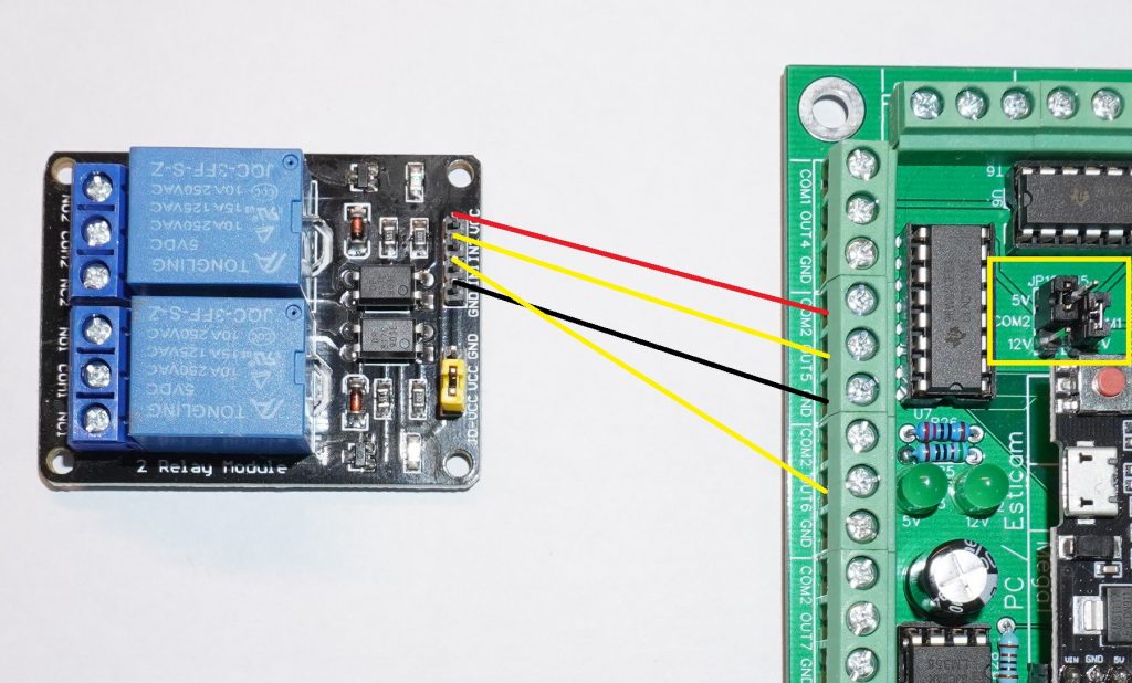
The following picture shows the connection of a 5V relay. COM2 is set to 5V. Then VCC is connected to COM2 (5V to VCC) and GND to GND. Switching is done with OUT5 and OUT6. As soon as these are triggered in Estlcam there is GND. If the relay does not switch, the jumper on the relay must be changed once. The jumper is yellow on the picture and under the connections for GND,IN1,IN2,VCC.
Plug-on drivers / External motor drivers
The OPEN-CNC-Shield supports plug-on drivers such as the A4988 or DRV8825 as well as the connection of external motor drivers. It is up to you what you decide to use. In general it can be said that external drivers have a much higher cost, but support higher currents and do not need such a good cooling. For Nema 17 motors with about 2A power the plug-on drivers should be completely sufficient with good cooling. If you want bigger/stronger motors/servos/”closed-loop motors” you should rather deal with external drivers. You can also start small and upgrade to external drivers later.
Plug-on driver
All changes should always be made in the de-energized state. Please also make sure that the drivers are plugged in the right way! There are differences between A4988 and DRV8825 drivers! If a driver is plugged in the wrong way and the board is powered up, the driver is most likely defective.
Microstepping
The microstepping of the plug-on drivers is set with jumpers. These are located on the board just below the respective drivers. This setting can therefore only be made if the drivers are not plugged in.
With microstepping you can further reduce the steps of the motor. For example, a typical stepper motor has 200 steps for one full revolution. If you set the microstepping to 1/8 step this means: 200 × 8 = 1600 – 1600 steps are needed for a full rotation. The higher the microstepping setting, the lower the holding torque of the motors. In general you can experiment with these values to see which ones work best for your own machine. Often manufacturers also indicate how the microstepping should be set. If you have to choose a setting here, it is essential to tell the software about it.
| MS0 | MS1 | MS2 | Mikroschritte |
|---|---|---|---|
| 0 | 0 | 0 | 1 – Full Step |
| 1 | 0 | 0 | 1/2 Step |
| 0 | 1 | 0 | 1/4 Step |
| 1 | 1 | 0 | 1/8 Step |
| 0 | 0 | 1 | 1/16 Step |
| 1 | 0 | 1 | 1/32 Step |
| 0 | 1 | 1 | 1/32 Step |
| 1 | 1 | 1 | 1/32 Step |
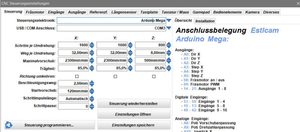
Here is an example of Estlcam. The microsteps should work like this for a MPCNC milling machine. In this example the jumpers are set to 1/8 step for the x and y axis and 1/4 step for the z axis.
Inserting the drivers
Please only in powerless state!
Here it is important to pay attention to the correct orientation, which can differ between the different driver types.
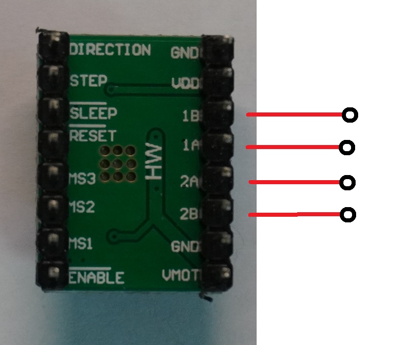
I always do it by looking under the drivers and looking for the position of the motor connectors(1B, 1A, 2A, 2B) and make sure to align them towards the 4Pin header for the motor.
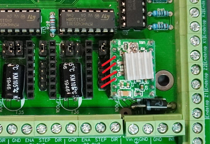
This is how it looks from above. The motor connections go in the direction of the pin header. Attention, the picture of a DRV8825 driver is different! Only pay attention to the motor connections!
Fault Jumper
This jumper can be found next to each driver. Labeled JP5, JP8, JP4, JP3, JP9, JP12.
If the DRV8825 drivers are used, this jumper remains open or is not set. The drivers give a signal when they are overloaded, which you could use. For the A4988 drivers this jumper must be set! With this jumper the driver is supplied with 5V.
Set driver current
The drivers have a potentiometer with which the current or voltage can be adjusted. This is calculated as follows: Maximum current of the motors divided by 2, i.e. for standard Nema 17 stepper motors with 2A a reference voltage of 1V( 2A / 2 = 1). At this voltage, however, the drivers need very good cooling. With the MPCNC the drivers are usually set to 0.7V. But you still have to cool the drivers ;-).
The setting of the voltage has to be done in the powered state. Therefore you have to be very careful not to slip off and cause a short circuit. In the following video I have shown how to adjust the motors:
Connecting the motors
The motors are connected to terminals J4, J7, J1, J2, J10 and J11. Dupont connectors can be used for this purpose. Here for example a set with pliers: ![]()
The following connection diagram should help:
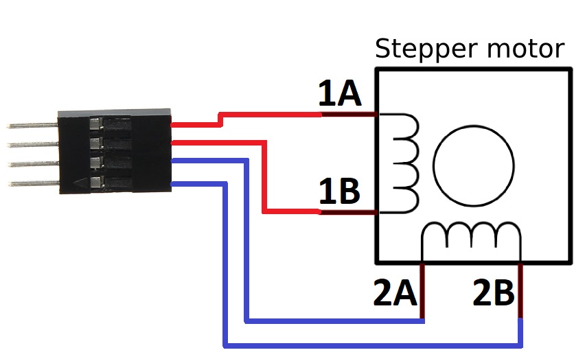
To find out which cables belong together you can simply make a continuity measurement. The connections 1A and 1B should have a continuity. Just like 2A and 2B.
External motor drivers
There are a lot of different external drivers. If you use external drivers, the Microstepp configuration is done directly on the driver and not on the board. So the jumper setting does not play a role on the board anymore. Also the board needs now only a fraction of the current, because the drivers are operated directly with the motor current. Here is an example for TB6600 drivers:
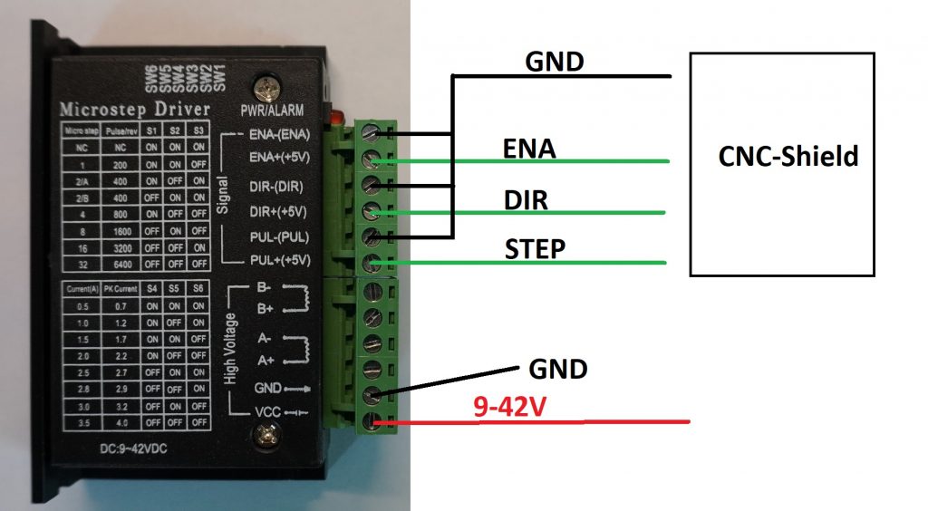
On the OPEN-CNC-Shield there are 4 outputs for each driver. Once Enable(ENA) to switch the motors without current, then DIR for the direction of rotation and STEP for the steps. Finally GND is connected to all negative poles. In the “High Voltage” area the stepper motor and the power supply is connected.
Configuration of the axes
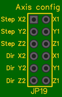
Here you can connect the axes with each other. Depending on what you use the shield for, you can configure the axes. For example, if you set a jumper at “Step X2” and “X1” the steps of both axes are connected / equal. The same applies to the other jumpers.
Axes in Estlcam
When using Estlcam, all jumpers should be set. Estlcam supports only three axes(x, y and z). By setting the jumper the motors for x1 and x2 do the same steps and rotate in the same direction. The same applies to the other axes.
Axes in LinuxCNC
When using the LinuxCNC adapter v1.0, the jumper for the z-axis can be left free for both “Step” and “Dir”. This allows the motor Z2 to be used for another axis. So you could move 4 axes in LinuxCNC.
Spindle control
The OPEN-CNC-Shield offers various possibilities of spindle control. Among other things it is possible to switch it on and off or to regulate the speed.
Attention! Danger to life! Have the milling motor connected by an electrician!
The picture below shows the terminals for connecting a spindle.
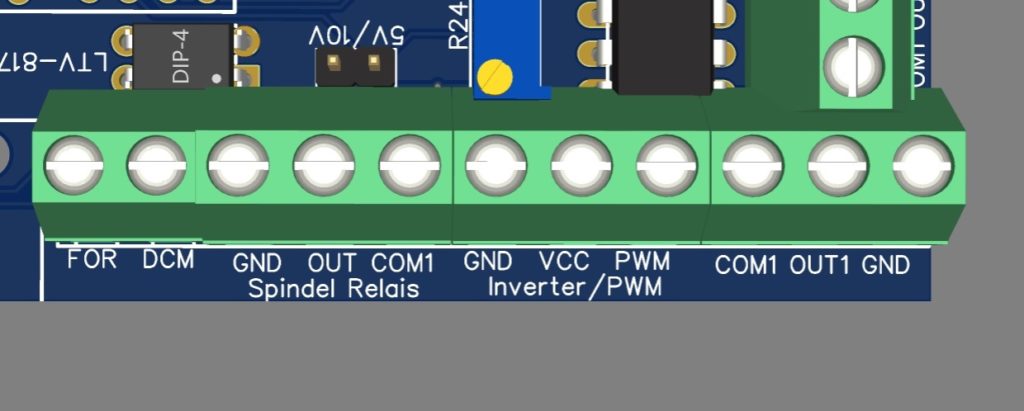
| Labeling | Function |
|---|---|
| FOR / DCM | This connection is for the control of a frequency converter (FU) e.g. for the typical Chinese spindle. This is used to switch the FU on and off. For more details see connection of a frequency converter. |
| Spindel Relais GND/OUT/COM1 | A relay for switching on a spindle can be connected here. It is also possible to connect other hardware which should be switched on at the same time as the spindle via a relay (for example the pump of a water-cooled spindle). The output OUT is connected to GND (ground) in the switched state. COM1 is set by the jumpers on the board and can be either 5V, 12V or a self applied voltage. NEVER apply 230V here! More about this under connection of a milling machine. |
| Inverter/PWM GND/VCC/PWM | These connections are used to control the rotation speed. Between GND and VCC there is an analog signal between 0-10V. If the jumper JP18(5V/10V) is set there is an analog signal between 0-5V. This signal can be adjusted with the adjustable resistor R24. See Calibrate analog signal. Between PWM and GND there is a PWM signal (0 or 5V). This signal can be used e.g. for the connection of a laser, see connection of a Laser. |
Calibrate analog signal
The following video shows how to calibrate the analog output to 10V. By the way, this step is only necessary if a spindle with external speed control is connected.
Briefly summarized:
- PSupply the board with power.
- Connect Arduino to computer with Estlcam
- Set the multimeter to DC measurement and connect it to the terminal inverter/PWM. The negative pole is connected to GND and the positive pole to VCC.
- Select the Arduino Mega with the correct port in the CNC control of Estlcam.
- Under the Milling Motor tab, load the settings for the China spindle.
- Program the controller.
- Press the button to start the spindle and type the command “pwm100” in the command line.
- Make sure that the slider for the spindle speed is above 100% and then turn the adjusting screw on the potentiometer until the multimeter shows about 10V.
- Done.
Connection of a milling machine (on/off)
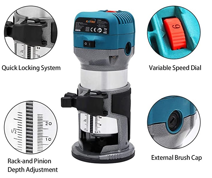
Normal air-cooled milling machine. Speed control on the milling machine itself. Attention, loud.![]()
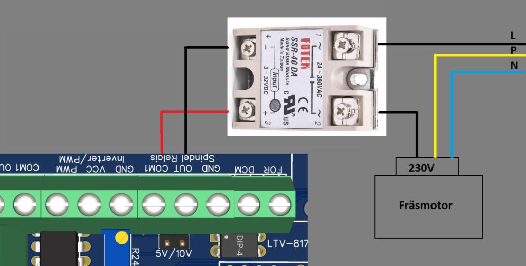
The milling motor is connected to the control system via a relay. A solid state with zero-crossing switching should be used. Here is an example: Ebay – RM1A23D25. Attention, depending on the current consumption the relay can become hot and must be cooled. Here is for example a suitable heat sink: Amazon – Cooler.
The typical mechanical 5V relays for e.g. Arduinos are not suitable.
Connection milling machine with external speed control
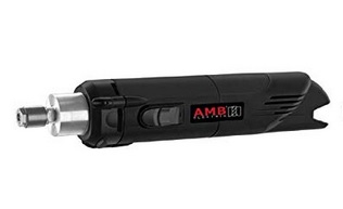
Milling with external speed control such as an AMB 1050 FME or also from Mafell
Amazon – AMB 1050
Amazon – Mafell FM 1000
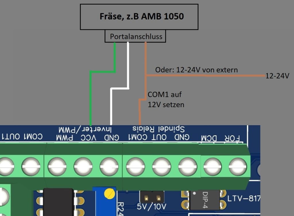
Here the milling machine can be connected directly to the OPEN-CNC-Shield without a relay. The brown cable can either be connected to COM1, or directly to the power supply unit for powering the board.
Connection of a frequency converter (China spindle)
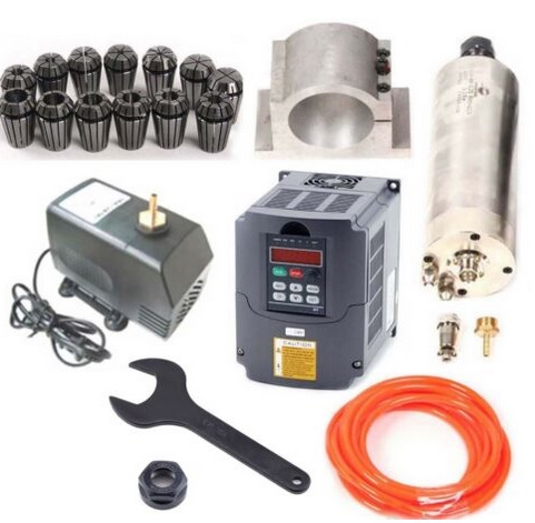
Typical water-cooled China spindle. I also own one myself. Once it runs, it runs 🙂![]()
![]()
![]()
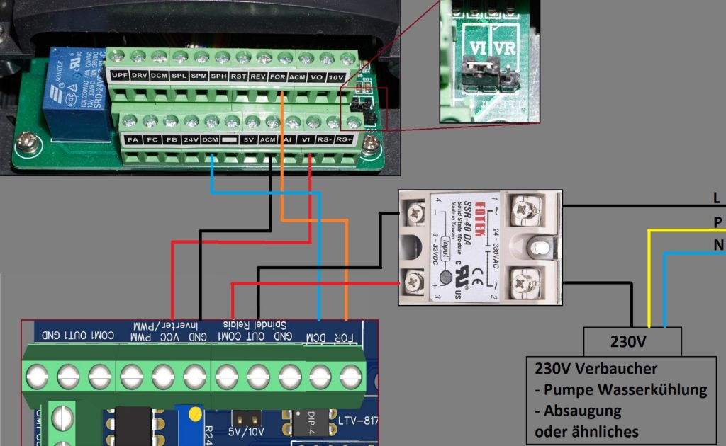
Connection table:
| OPEN-CNC-Shield | Frequency converter | Explanation |
|---|---|---|
| FOR / DCM | FOR / DCM | Switching the frequency converter on and off. Current flows from FOR to DCM. Here the direction of flow is decisive. Should the spindle not switch, although it “should” switch the cables and try it out if it works. |
| Inverter/PWM GND and VCC | ACM(GND) and VI(VCC) | This connection is for speed control. Normally 0-10V. Adjustable to 0-5V by jumper JP18. With my FU you could also set with how many volts the input should work. For this please look into the manual of the FU. |
| Spindel Relais OUT / COM1 | Optional: Here you can for example connect a relay to switch pumps or suction etc. Attention: Depending on the amount of current consumption the relay can get hot and must be cooled! |
Attention, for the speed control to work, the jumper for VI/VR must be set as shown in the picture above. Otherwise the speed is still controlled by the potentiometer on the FI.
More information about setting and connecting the frequency converter can also be found on the Estlcam page. There this is again very well described: Estlcam – Chinaspindel
Connection of a laser
Here is an example of the connection of a laser. I have used the following laser: ![]()
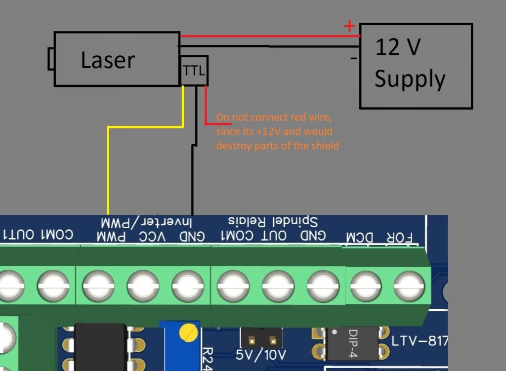
The laser I use needs 12V, I get it from an external power supply. Since the laser only runs when a signal is given out via PWM, I save myself the trouble of supplying the laser with power via a relay. But that would also be possible. The relay would then be connected to the “spindle relay” connector on the board, just like the spindles.
For the TTL of the laser to work it needs a clean PWM signal of 0 or 5V. This can be found on the board at the “PWM” connector. The “VCC” connector does not work even if the jumper is set to 5V. VCC only outputs an analog voltage.
Important, my laser had 12V on the red cable of TTL. Do not connect it to the board. Components can be destroyed. It is enough to connect the yellow signal cable and the black GND cable.
How the whole thing is controlled and works on the software side I show in this blog post: LaserGRBL mit dem OPEN-CNC-Shield
Link to the customized GRBL firmware: Gitlab – grbl
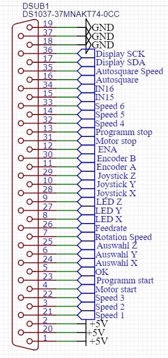
SUB-D 37 port
This connector leads many of the Arduino pins to the outside and serves as an interface for external controls such as handwheels, joystick, buttons etc.
External wireless panel
This control panel is wireless. More information is available on this page: Wireless Control.
Extension Panel(connection by cable)
The extension panel is connected by cable and offers a lot of possibilities for external controls. For this I have created a page with more information:
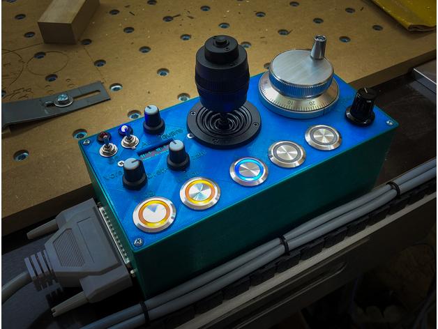
Extension Panel
Image by Carsten Schröder
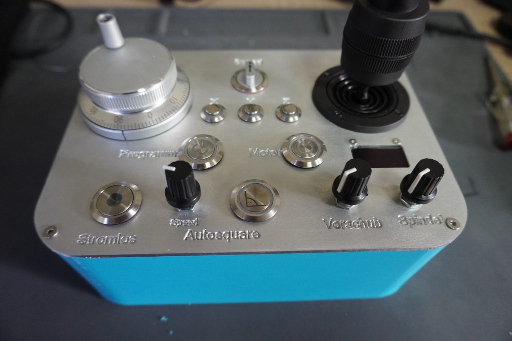
Handwheel
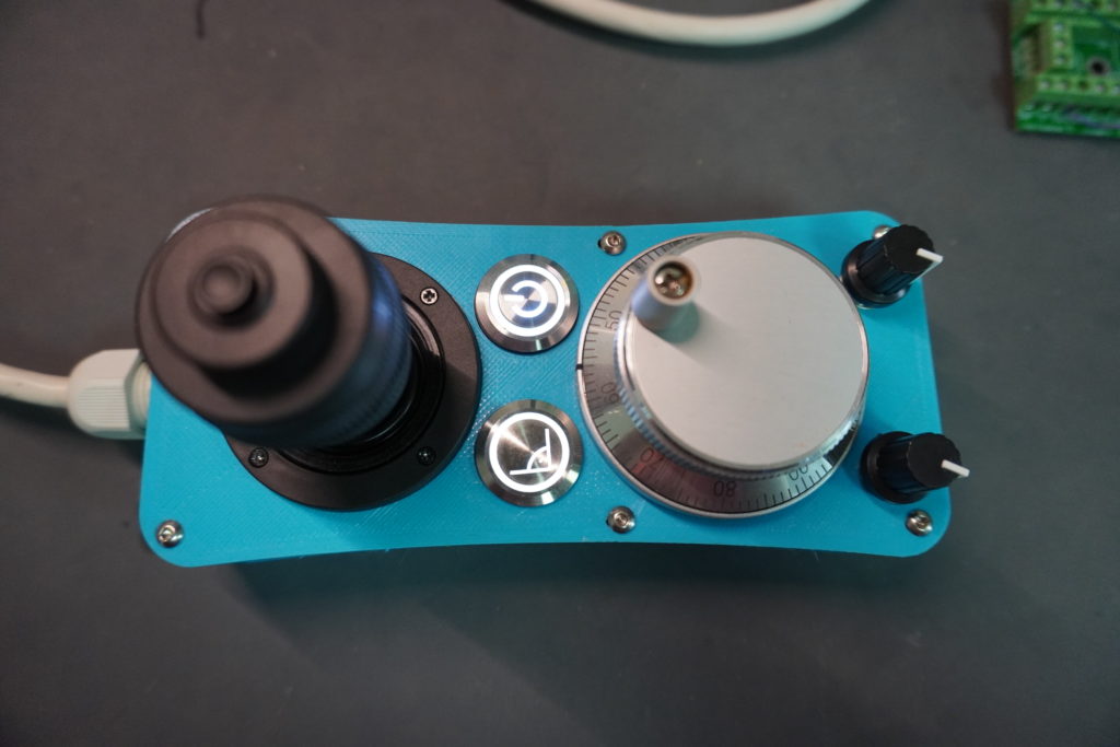
This handwheel is nice and small and offers the most important operating elements. It is connected by cable. There is an article with assembly instructions: DIY Handrad unter 70€
Breakout Board / Own development
You would rather have something of your own? That is also no problem. You can order and connect such an adapter:
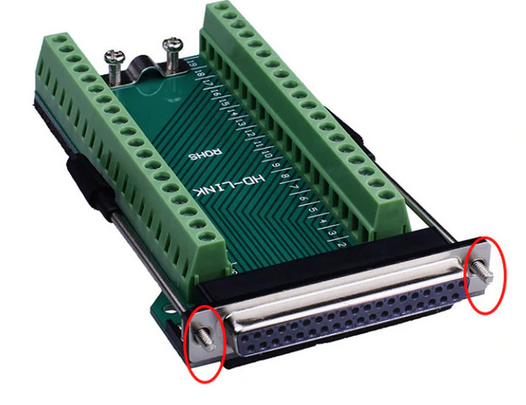
SUB-D 37 Breakout Board![]()
![]()
There you can connect all controls and follow the instructions on the Estlcam homepage: Estlcam Handrad – To do this, simply connect to the pin out shown below.
SUB-D 37 Pinout
Fan port
It is possible to connect a 2 pin fan or a 3 pin fan with 12V to the 4 pin fan connector on the board. Please pay attention to the correct polarity of GND and +12V. These are marked on the board.
Controlling a 4Pin fan with speed control only works with the second Arduino Mega! Without the second Arduino, a PWM fan will probably not turn at all, or only very slowly.
Second Arduino Mega
The second Arduino Mega mini pro is optional and can be used to add more functionality. This includes autosquaring, temperature dependent fan control, control of a display etc.
Software installation / configuration
The software for the Arduino is located in Gitlab – Timos Werkstatt – Repository: open-cnc-shieldSketch
Autosquaring
Autosquaring of the axes is especially useful for DIY milling machines and is intended to ensure that the axes are perpendicular to each other. Especially with the MPCNC or Artisan, which mostly come from the 3D printer, there can be problems with squareness, which hopefully will be solved by this. With autosquaring, all motors for which autosquaring is activated are driven against their respective end stops. In order for the axes to be at right angles, the end stops must be aligned accordingly.
Attention, to use autosquaring, a push button / switch must be connected to the appropriate pin of the SUB-D 37 connector. If the extension panel or radio panel is used, connections are already provided and led out.
In this video I show how to use Autosquaring and what it is:
Autosquare configuration
Autosquaring is configured and activated by jumpers.
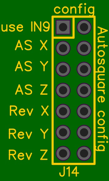
Here you can define for each axis individually whether it is active or not. The direction can also be changed. So if the motors are running in the wrong direction after starting the autosquaring a jumper at e.g. “Rev X” will make the motors of the x-axis run in the other direction. This setting only applies to the autosquaring mode!
If the jumper at “use IN9” is set, input 9 is triggered when autosquaring is started and can be configured in Estlcam as an end stop for example. This way Estlcam thinks that an end stop has been triggered and does not try to move the milling machine itself.
Autosquaring for an axis only makes sense if there are also two motors for this axis.
Connect end stops
The end stops must be connected to the correct inputs for autosquaring to work. Here is a connection table:
| Motor | Endstop |
|---|---|
| X1 | Input 5 |
| X2 | Input 6 |
| Y1 | Input 7 |
| Y2 | Input 8 |
| Z1 | Input 3 |
| Z2 | Input 4 |
In the standard version of the program, NO ( = normally open) end stops are assumed. If the endstops are connected as NC, this must be changed in the Arduino code. See the following line at the beginning of the Arduino code:
// Use HIGH for normally open endstops and LOW for normally closed endstops
const uint8_t endstopStateTriggered = HIGH;
Fan control with PWM
On the board is a 4Pin fan connector. Here all kinds of 12V fans can be connected. Among them a 2Pin fan (only with GND and +12V), a 3Pin fan or a 4Pin fan with speed control.
On the second Arduino the temperature of the onboard temperature sensor is read every X seconds by default and the fan speed is increased accordingly when the temperature rises. This only works with a 4Pin PWM fan, and there are also differences in frequency. I have tested the board with the following fan:
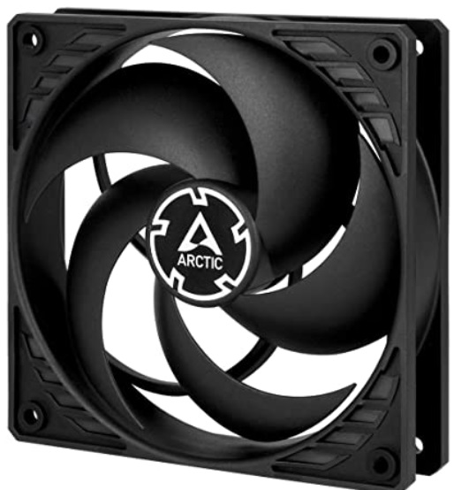
12V PWM Fan: ![]()
This fan is pleasantly quiet and works great with the speed control.
Whereby surely also other functioning. I just tested this one.
External temperature sensors
It is possible to connect additional external temperature sensors. For this purpose there is a terminal with the label “Temp DS18B20” on the board. Here one or more sensors of the type DS18B20 can be connected. I do not know exactly how many, but certainly more than you need. These are also available in a waterproof version. So it makes sense to keep an eye on the cooling water temperature for example :-).
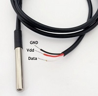
DS18B20:
![]()
![]()
![]()
By default, only one sensor is read out there and shown on the display of the operating panel. If you want to read out and process several sensors or react to the temperature in any way, you have to do it yourself and program the function on the Arduino yourself. In time I will make a contribution to this.
LinuxCNC
Connection of the adapter
Unplug the arduino mega mini for estlcam on the open-cnc-shield and plug in the adapter for LinuxCNC
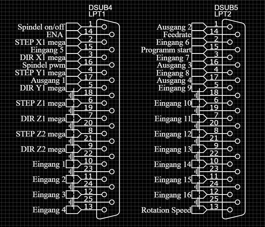
Connect LPT / Parallel Port
Here is the pin mapping of the LPT ports:
FAQ – Frequently asked questions
Why does input 8 in Estlcam always show triggered?
This is because Estlcam uses the Arduino pin D13 for input 8 and unfortunately this is usually connected to the internal LED of the Arduinos. Fortunately this is superfluous and can be easily removed. I always do this with a cutter knife and lever them out.
Of course you can also be more careful and desolder them. Then you have the possibility to solder them back on later. In this short video I show how I always do it: