Preparation
Basic equipment
Soldering station
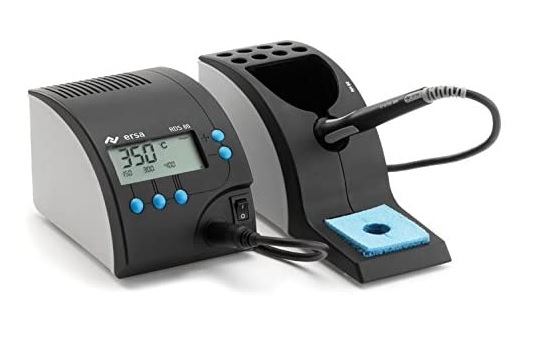
I use a somewhat higher quality soldering station from Ersa and am very satisfied. Mainly I use the fine soldering tip with 0,8mm diameter.![]()
PCB holder
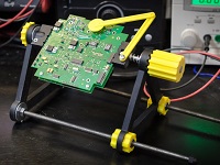
You can printed by yourself from the 3D printer.
Thingiverse
Solder

I only solder with leaded solder, I find it much easier than with lead-free solder. But I also don’t want to exclude that I am simply too stupid 😅. I linked what I bought.![]()
Tweezers
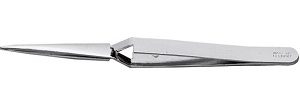
In my opinion a must have. With this the components can be held in place very easily. You fix the component and then turn the board around and you can easily solder the component firmly. It comes in different versions and lengths.![]()
![]()
![]()
Desoldering pump
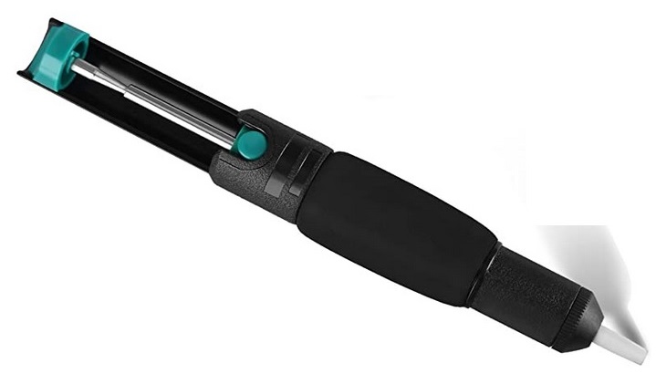
In case pads bond or too much solder is applied. For me such a cheap one up to €5 is perfectly sufficient.![]()
![]()
![]()
Side cutters / cable cutters
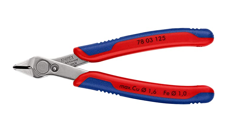
I guess I don’t have to explain the function 🙂![]()
![]()
Foreword
In order to always get good access to the components, I can only recommend to work from the lowest to the largest components. You should pay special attention to soldering cleanly and only put solder on the pads provided. If there is too much solder on one pad, or if two pads are connected, you can use a small desolder pumps to remove the excess solder.
It is also advisable to prepare all the necessary components and to make sure each time that the right component is soldered in the correct orientation. I don’t know how many times I installed male pin headers instead of female ones or vice versa. It is extremely difficult and annoying to remove them again. So it is better to check too much if everything is correct before soldering the component.
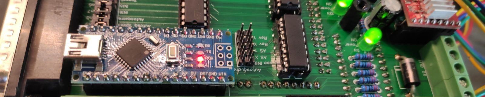
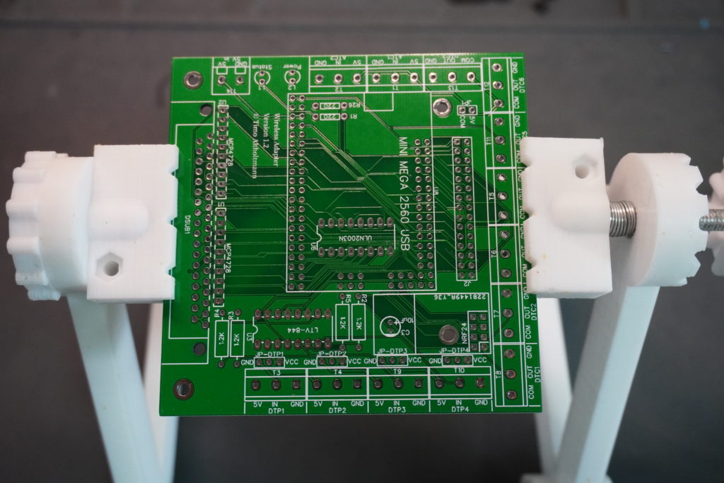
Arduino mega mini
I always solder them first before I start soldering the boards.
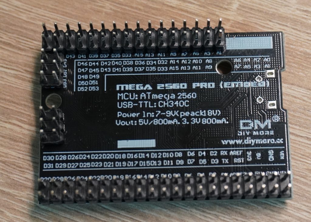
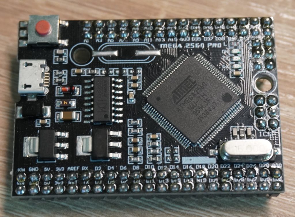
Contrary to many pictures you find online, I decided to let the pin headers point down. This way you can still see the LEDs and press the reset button.
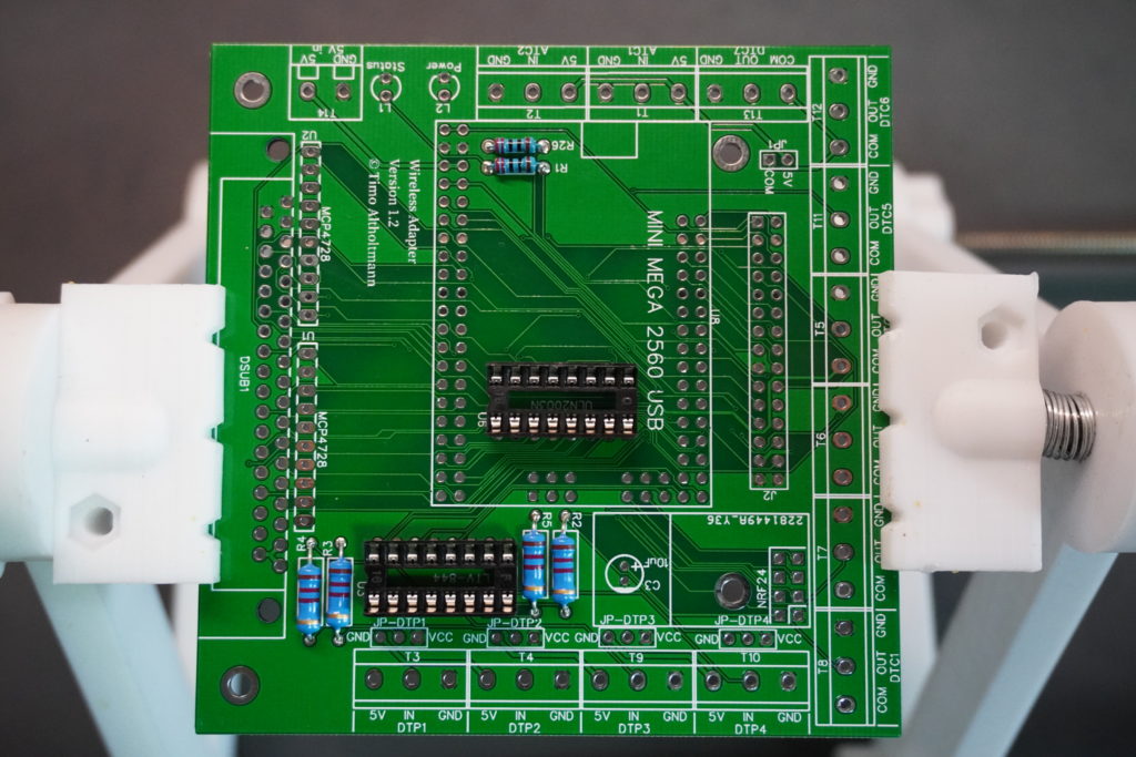
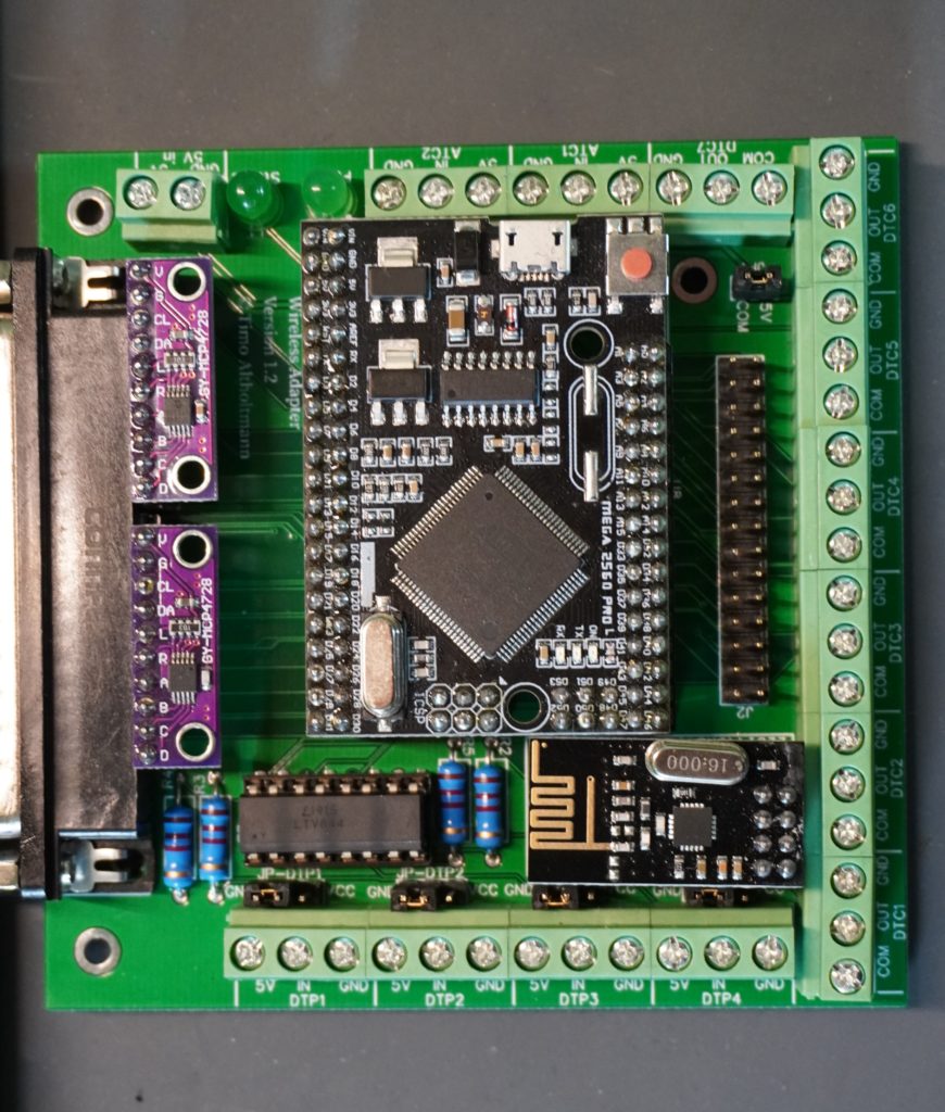
Wireless Adapter
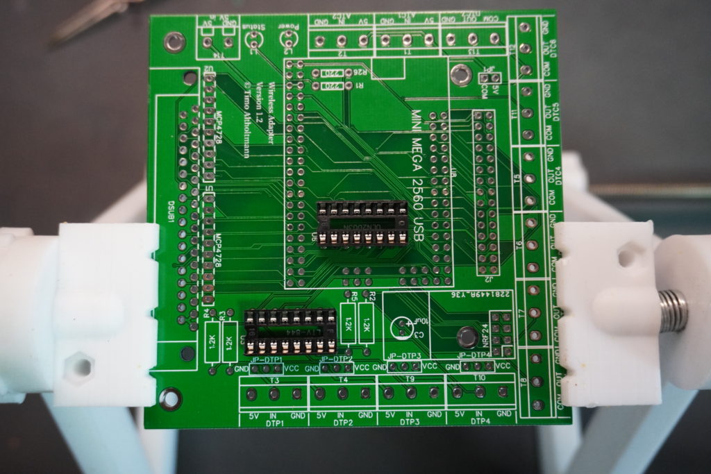
ICs
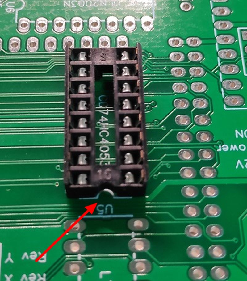
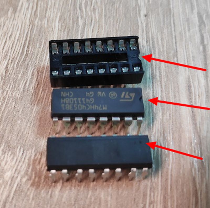
When soldering the IC sockets, it is important to pay attention to the right direction. The notches should be on top of each other as shown here in the picture. The ICs are also inserted in such a way that the notches lie on top of each other. Some ICs have a dot instead of a notch. In this case the point must lie over the notch of the socket.
You can also leave out the sockets and solder the ICs directly onto the board, but then it is very difficult to remove them, either because of a defect or because you accidentally put them in the wrong way.
Widerstände
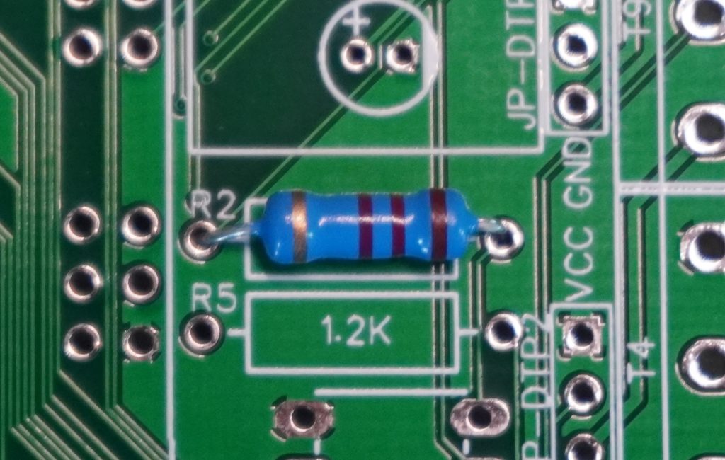
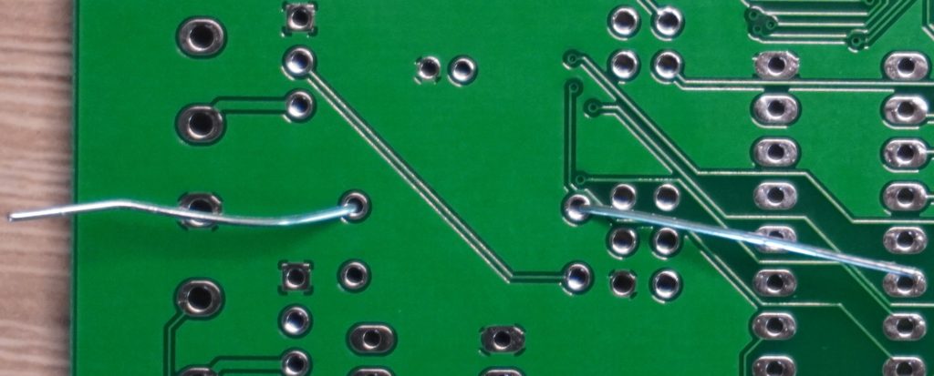
The orientation of the resistors does not matter. These can be put into the holes provided for it and then soldered. To prevent them from falling out again and again you can simply bend the legs on the other side. After soldering the legs are cut off.
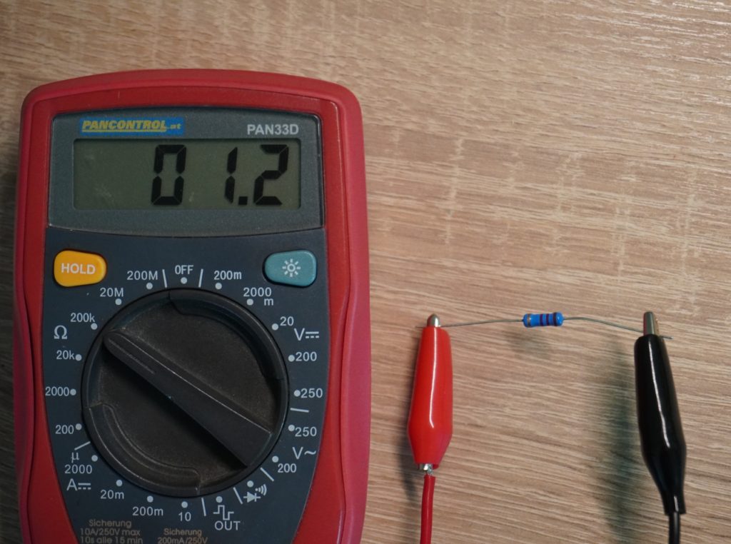
If you want to determine the resistance value you can either use a measuring device or use the color codes to determine the value. There are also converters in the net, for example here: Calculator.
Capacitor
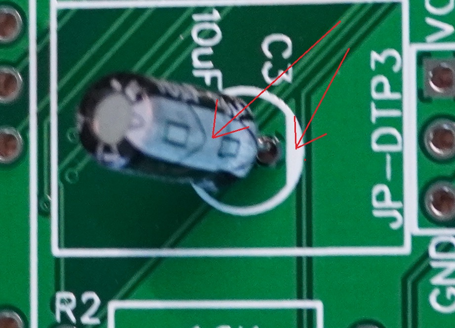
With capacitors it is very important to pay attention to the polarity. They usually have a white line on the side which marks the negative pole, this line must match the white mark on the board. In addition the leg of the negative leg is always the shorter one.
MCP4728
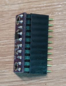
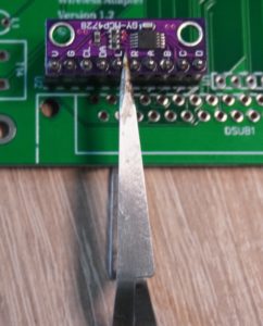
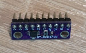
The MCP4728 Digital to Analog Converters are first equipped with a pin header. Then a female connector strip is plugged on and soldered on the board. The alignment is important here.
Remaining pin headers
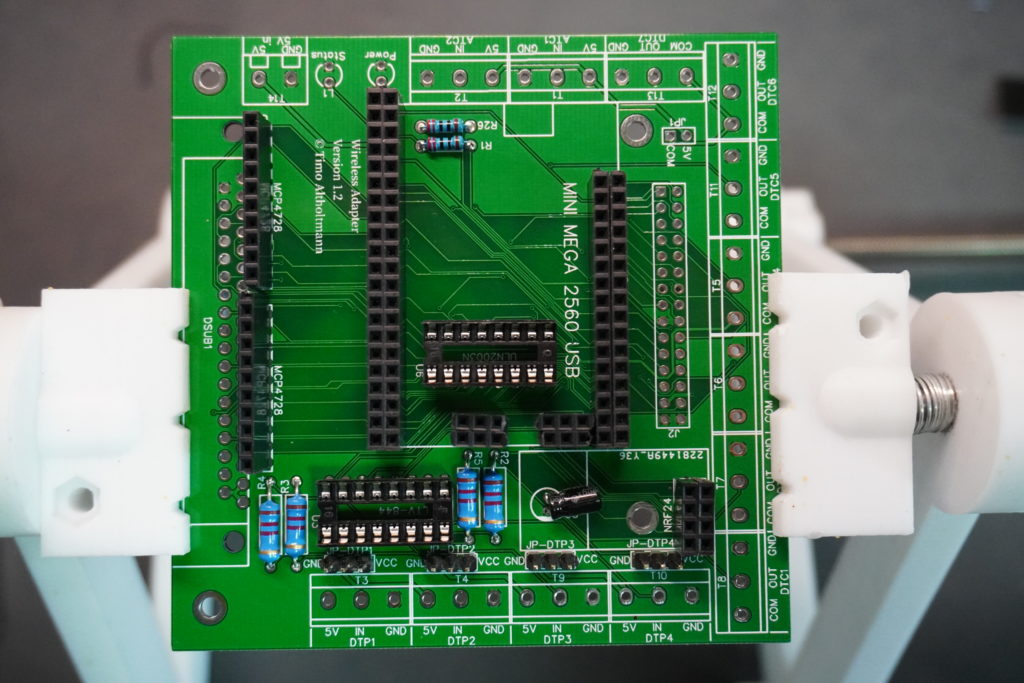
LEDs
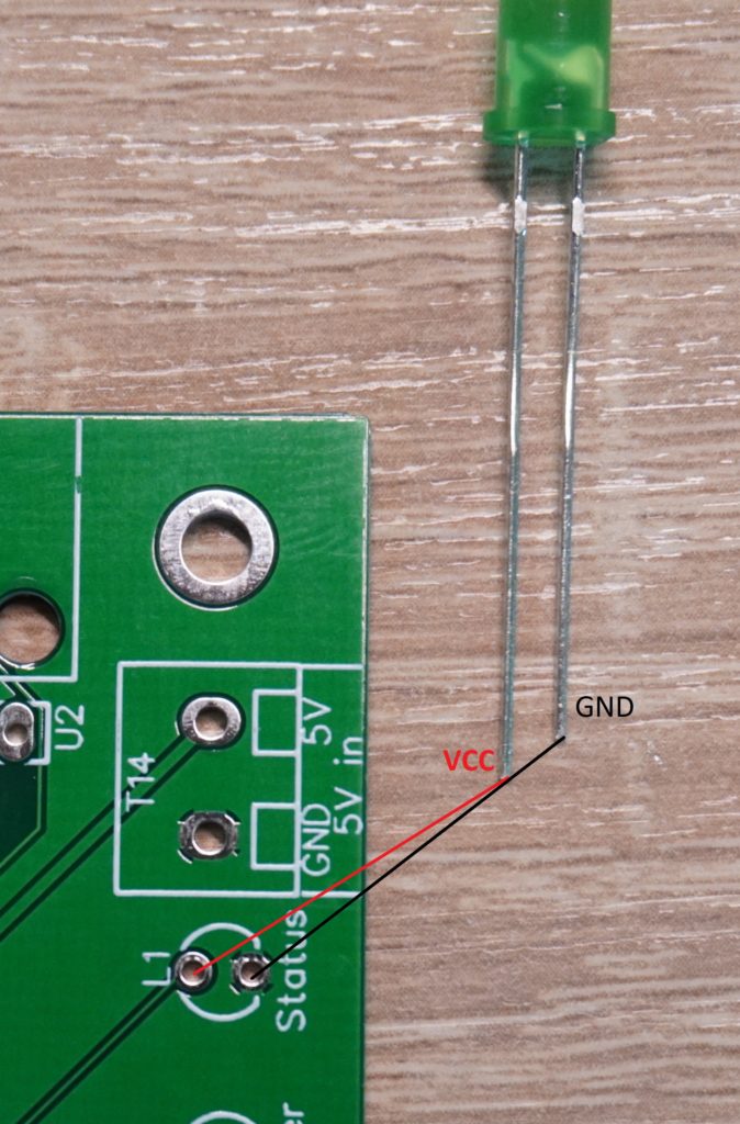
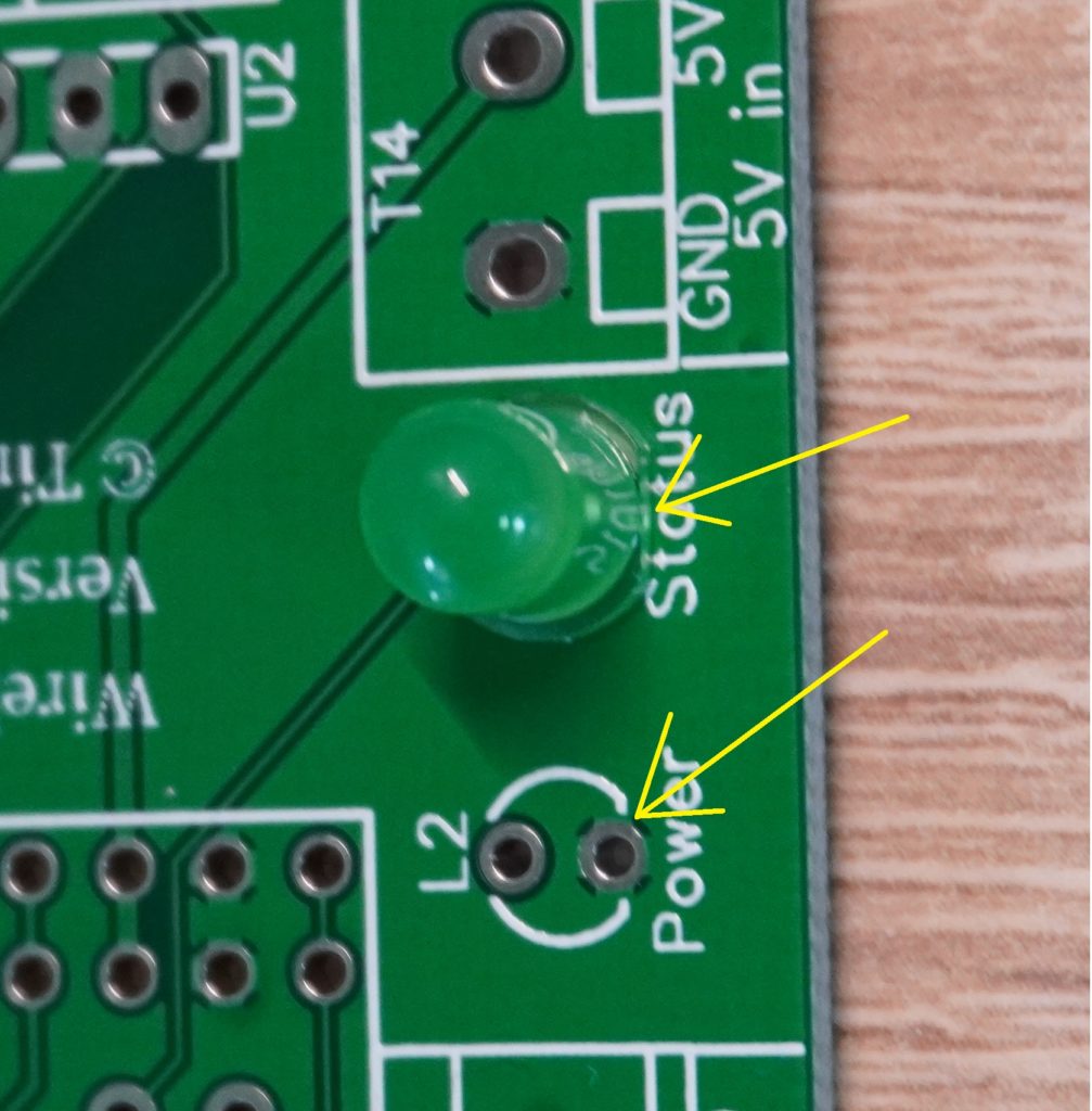
The LEDs can be soldered directly on the board as shown in the images. If you want to lead them out of a housing it is strongly recommended to solder pin headers instead. Then you can lead the LEDs later by cable from the board to the housing.
With LEDs, the alignment is crucial. The shorter leg of an LED is also here the minus pole. In addition, the LED is not quite round and has a small notch on the side. This also marks the minus pole and must correspond with the flattened side on the board.
Terminals and insertion of the components
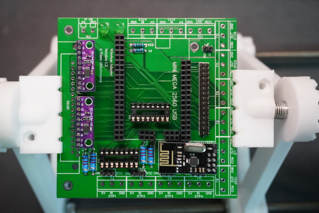
Finished – next steps
The assembly is now complete. The programming of the Arduino and further information can be found in the documentation.
Wireless Panel
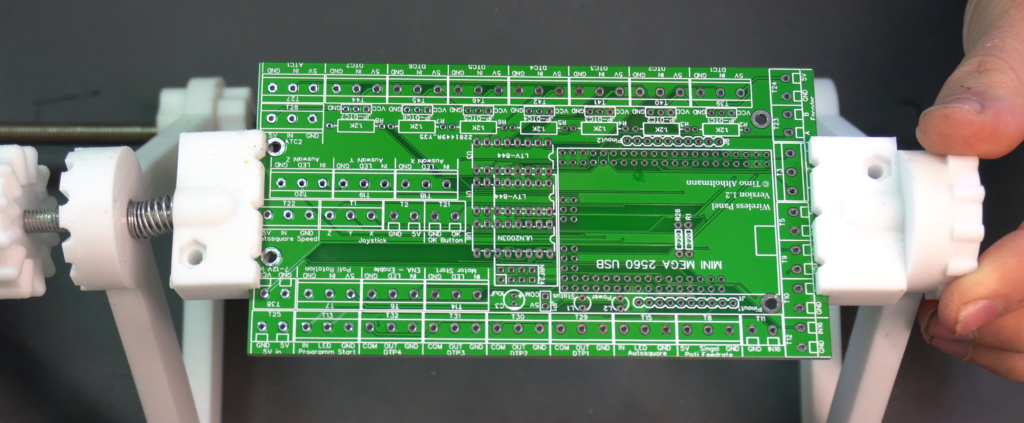
How to solder the individual components is already described in detail above for the Wireless Adapter.
Video
Here is another video that shows everything in fast forward.
Connect / prepare components
Here I will try to go into the specifics of the different components and their wiring.
Joystick
I can recommend the 3-axis or 4-axis joystick here. With the 4-axis joystick there is a button on the top of the joystick, which I use e.g. to zero the axes.
3-Axis Joystick
The wiring is a bit tricky here, so here are some pictures to illustrate:
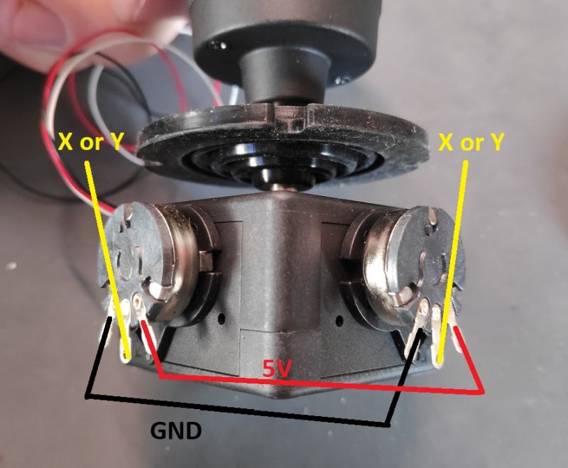
GND and 5V of the x- and y-axis can be connected. If the axes should go in the wrong direction afterwards, you can either exchange GND and 5V, or simply check the box “Reverse axes” in Estlcam.
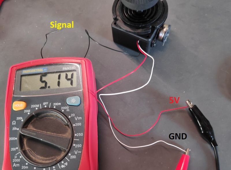
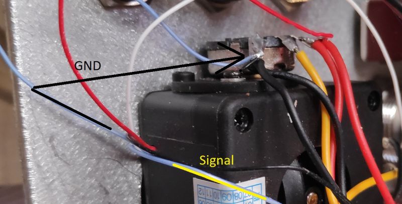
Here is the wiring of the z-axis on my 3-axis joystick. Should the axes go the wrong way round you can swap GND and 5V again. To be sure which cable is for what, you can use a multimeter. Just set it to measure resistance and test the cables one after the other. You have found GND and 5V if the resistance does not change when you turn the joystick. So this joystick has 5K Ohm throughout. Depending on the joystick this can also be 10K Ohm.
4-Axis Joystick
The wiring is exactly the same as for the 3-axis joystick above, the only difference being two more cables for the 4th axis (which is actually not an axis at all, but only a button).
The two cables for the button were blue on my 4-axis joystick. Since the switch is always connected to GND, one cable goes to GND and the other to the board for e.g. the OK button (zeroes the currently selected axis). To be on the safe side you can also connect the multimeter and this time you can do a continuity check. Connect the two cables to the multimeter, set the multimeter to continuity check and press the button of the joystick. Now a continuity test should be displayed.
Potentiometer
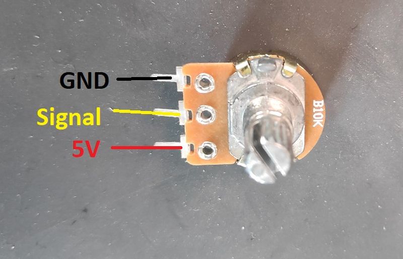
Again, if the potentiometer is the wrong way round, simply change GND and 5V.
Push button with LED
With the buttons I use on the pictures you can also swap GND and 5V.
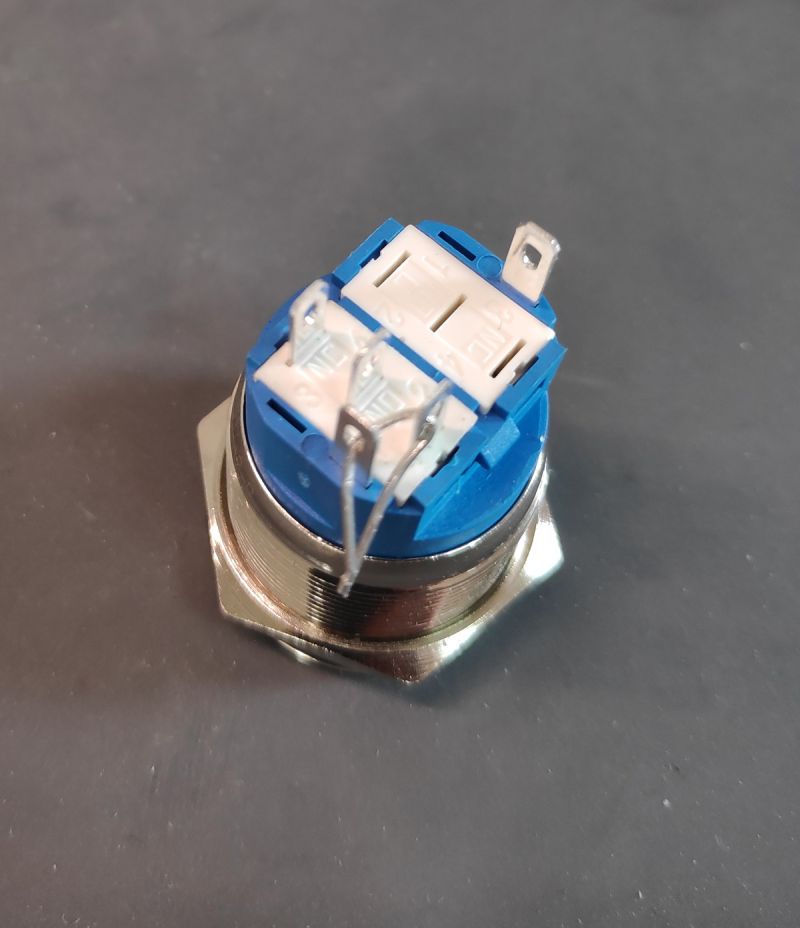
Here we can use the legs of the resistors. This makes soldering easier. The switching contact is connected with a LED contact. Both are then connected to GND on the board.
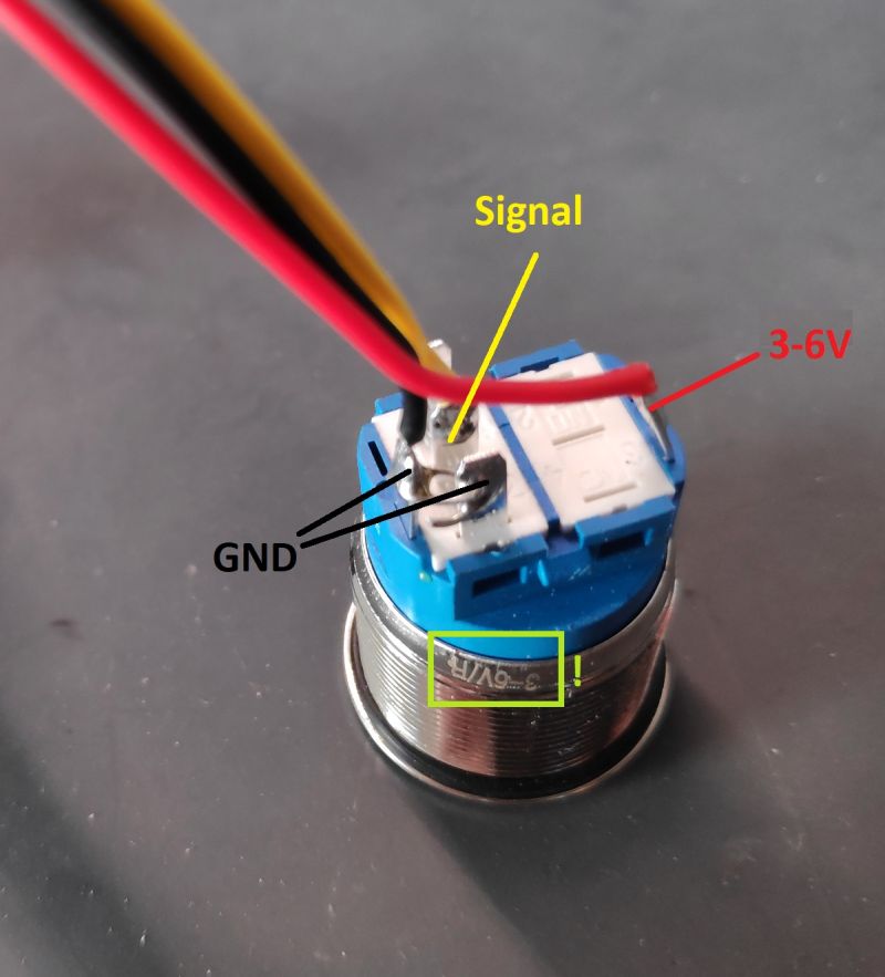
This LED of this button can work with 3-6V. Please pay attention how much Volt the LED of your button can handle. Under certain circumstances a series resistor must be installed. These are already planned on the panel boards and can be activated/deactivated by a jumper.
3-Position Switch
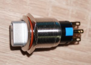
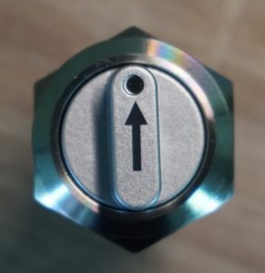
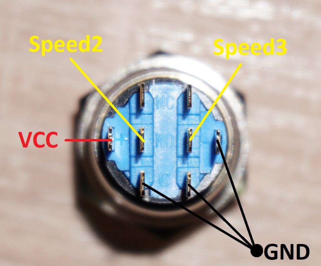
This switch is wired as shown in the picture above. In the middle position no contact is triggered. Estlcam has “Speed 1” active by default anyway, so we don’t need an extra cable for this and can leave the “Speed 1” connector free. “Speed 2” and “Speed 3” can then be connected as shown here. VCC or 5V is used for the power supply of the LED with this switch.