Jumper configuration / Terminals
Wireless Adapter
| Label | Function | Description |
|---|---|---|
| JP-DTP1-4 | Selection how the inputs are switched | VCC: The input triggers when IN 5-24V are applied. GND: The input triggers if IN GND is present. |
| JP1 | Power supply for the outputs | If the jumper is set, the outputs have just under 5V in the switched state. If this jumper is not set, even a voltage can be applied to COM. The voltage always applies to all outputs. |
| DTP1-4 | “Digital to Panel” | Digital inputs on the Wireless Adapter, which are available as outputs on the Wireless Panel |
| DTC1-7 | “Digital to Control” | Digital outputs on the Wireless Adapter, which have their corresponding digital inputs on the Wireless Panel |
| ATC1-2 | “Analog to Control” | Analog outputs on the Wireless Adapter, which have their corresponding analog inputs on the Wireless Panel. |
| T14 – 5V in | Power supply | Not required when the Wireless Adapter is connected to the Tillboard Extension or the OPEN-CNC-Shield In this case the adapter is powered via the D-SUB37 connector. |
Wireless Panel
| Beschriftung | Funktion | Beschreibung |
|---|---|---|
| JP1 | Power supply for the outputs | If the jumper is set, the outputs have just under 5V in the switched state. If this jumper is not set, even a voltage can be applied to COM. The voltage always applies to all outputs. |
| JP-DTC1-7 | Selection how the inputs are switched | VCC: The input triggers when IN 5-24V are applied. GND: The input triggers if IN GND is present. |
| DTP1-4 | “Digital to Panel” | Digital inputs on the Wireless Adapter, which are available as outputs on the Wireless Panel |
| DTC1-7 | “Digital to Control” | Digital outputs on the Wireless Adapter, which have their corresponding digital inputs on the Wireless Panel |
| ATC1-2 | “Analog to Control” | Analog outputs on the Wireless Adapter, which have their corresponding analog inputs on the Wireless Panel. |
| 5V in | Power supply | 5V power supply, for example through a powerbank. |
| 7-12V in | Power supply | Power supply, for example by a 9V block battery. |
Inputs
Wireless Adapter
Take a look at the OPEN-CNC-Shield inputs. The work the same way.
Wireless Panel
Take a look at the OPEN-CNC-Shield inputs. The work the same way.
Outputs
Wireless Adapter
Take a look at the OPEN-CNC-Shield outputs. The work the same way.
Wireless Panel
Take a look at the OPEN-CNC-Shield outputs. The work the same way.
Software / Firmware
The software can be found on Gitlab: Gitlab – Timos Werkstatt
Procedure for installing the software:
Wireless Adapter
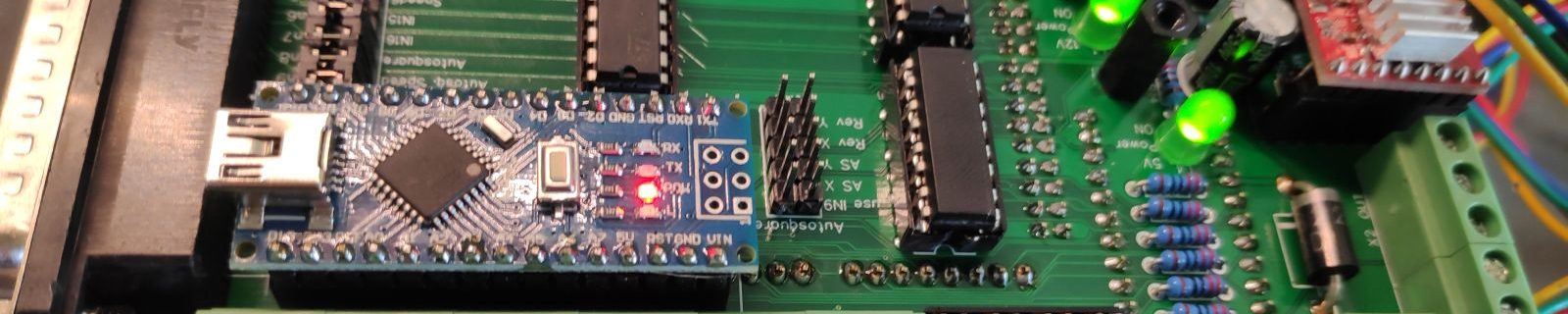
First the sketch changeMCPDeviceID is uploaded. The Arduino console/monitor should then say: Address changed successfully!
This sketch changes the I2C Device ID of one of the DAC converters and has to be loaded and executed only once.
After that the DAC converters must not be swapped. Otherwise you have to change the IDs again manually.
Then the normal wirelessAdapterSketch can be uploaded.
Wireless Panel
Here it is sufficient to upload the wirelessPanelSketch.