General
Introduction
This article is about a self-built handwheel / operating panel for CNC machines. I use this together with Estlcam and the OPEN-CNC-Shield. But any other software / board with the appropriate inputs should work as well.
You can set the controls as you like. I put the Fusion360 file at Thingiverse, so you can still customize the design.
Video – Presentation and assembly
Have fun watching:
Functions
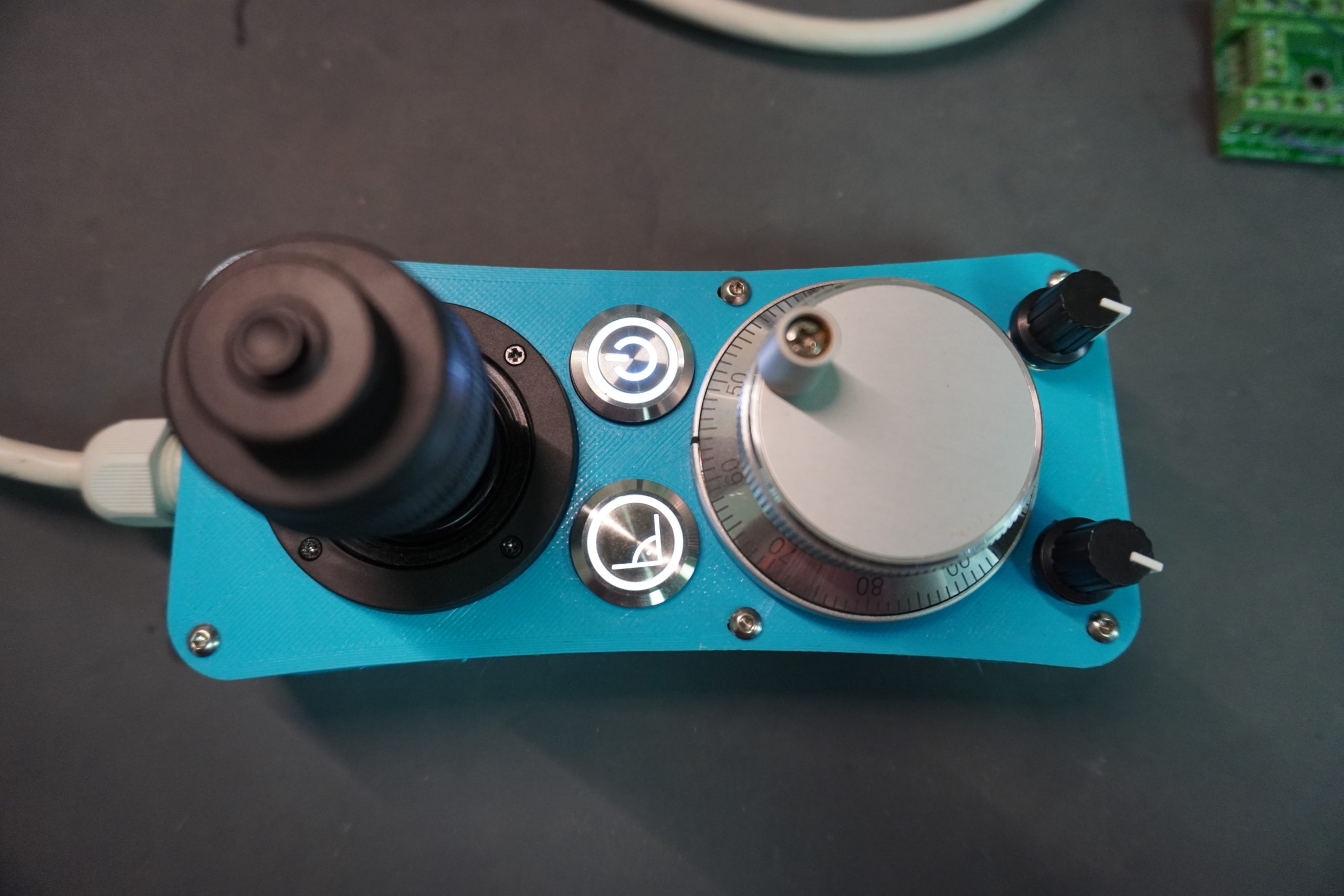
The panel as shown above, has the following functions:
- 4 Axis joystick for analog movement of the x, y and z axes. The speed can be configured in Estlcam.
- Handwheel for more precise / finer movement of the milling cutter
- Button for program start/stop
- Button to start Autosquaring(Tillboard Extension or OPEN-CNC-Shield is required)
- Potentiometer for spindle speed
- Potentiometer for the feed rate
However, you can also add or omit individual functions. Depending on what is needed.
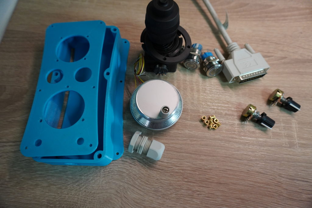
Required components
I am currently organizing a collective order for the controls. Just write to me on my Facebook page: https://www.facebook.com/TimosWerkstatt20/
| Component | Link |
|---|---|
| Housing I created the housing with Fusion360 and then printed it out with the 3D printer. When printing, make sure to turn the base plate and the lid in the slicer again, so that the printing is not in the air. Support is not needed. I printed with 100% infill and 0.2 layer height. For the screw connections I got M3 inserts. You can also print threads here, for this you have to adjust the model in Fusion. | Thingiverse |
Thread inserts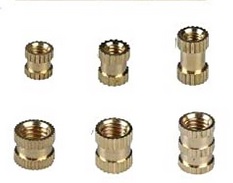 These threads are pressed into the 3D print with a soldering iron and provide an easy way to use reasonable threads in the print. | |
Cable gland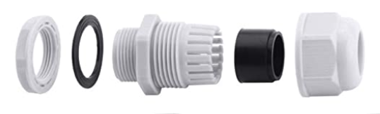 The cable gland also provides tensile strength for the cable. | |
Joystick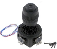 I have a 4 axis joystick with 10K ohms, but 5K ohms should also work. | |
Handwheel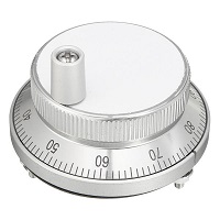 This is available with different diameters. I own the 60 mm version. Important is that it is 4-pin and designed for 5V. | |
Potentiometer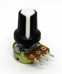 For the analog settings. Some with 5-10K Ohm should be used. | |
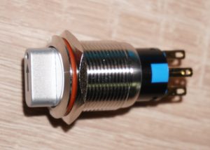
Push button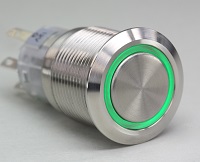 Available in different versions. Generally, some can be taken with or without LED. They are also available in many different diameters. For the housing above I used some with 19mm diameter. LED buttons can be used either with or without series resistor. If it should be which with LED, absolutely make sure that these can be operated with maximally 5V! 12V Leds do not work, or shine weakly | |
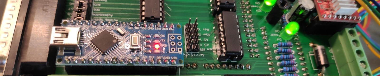
| Control line A cable is also required, this must have the appropriate number of wires. Basically every function needs one wire. For the example panel above a cable with 12 wires was needed. These are composed as follows: – 1x GND, 1x VCC – 4x for the joystick(x, y, z and the button on top) – 2x for the encoder – 1x push button start/stop – 1x push button autosquare – 1x Poti feed rate – 1x Poti spindle speed Since I still had half a D-SUB25 cable flying around here, I used that. If you use the Tillboard Extension or the OPEN-CNC-Shield you can also use the D-SUB37 cable directly. |
Assembly
The assembly is briefly explained in the video above and is generally not witchcraft. If there are any problems, please visit our Facebook group: CNC Werkstatt. Here (hopefully) help is provided 😉
Functional test
Before the handwheel is connected to the control unit, we should at least do the most important test and see if we have a short circuit in our wiring.
To do this, set a meter to continuity test and connect the terminals to GND and 5V. At this time do not apply current to the handwheel. With the power supply connected, operate all controls one after the other. Here never a continuity should be indicated, otherwise we have a short circuit.
Connect / prepare components
Here I will try to go into the specifics of the different components and their wiring.
Joystick
I can recommend the 3-axis or 4-axis joystick here. With the 4-axis joystick there is a button on the top of the joystick, which I use e.g. to zero the axes.
3-Axis Joystick
The wiring is a bit tricky here, so here are some pictures to illustrate:
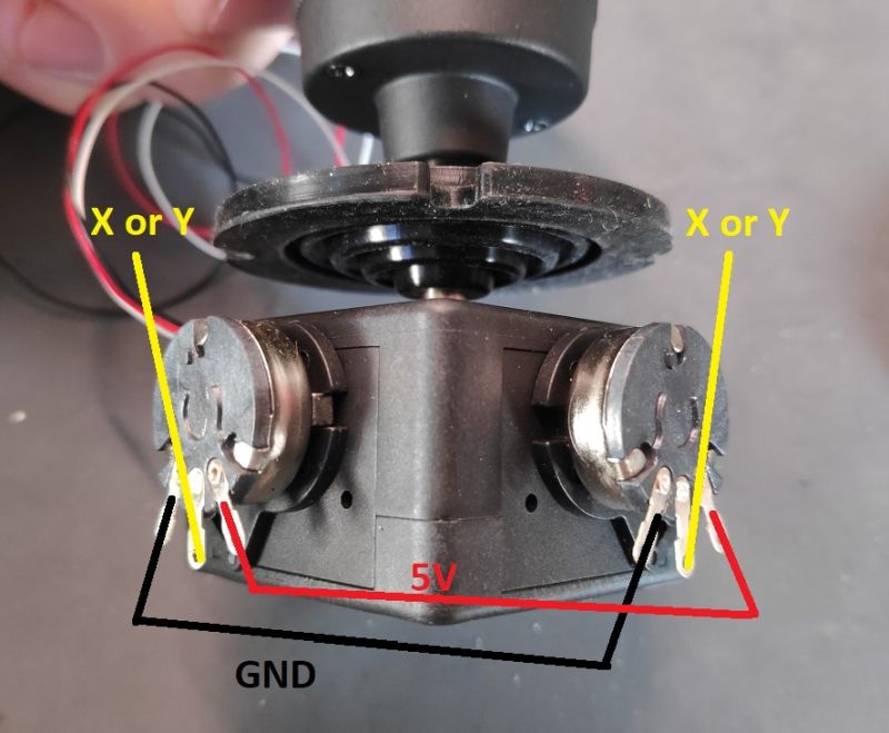
GND and 5V of the x- and y-axis can be connected. If the axes should go in the wrong direction afterwards, you can either exchange GND and 5V, or simply check the box “Reverse axes” in Estlcam.
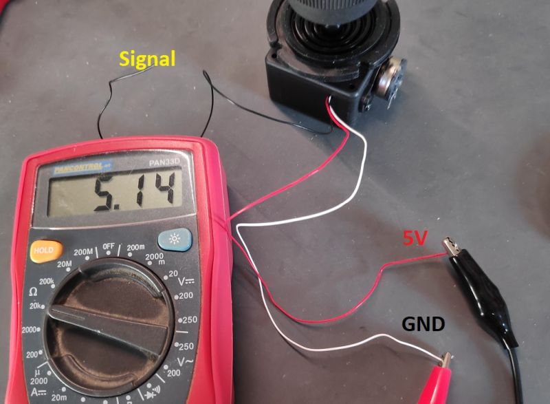
Here is the wiring of the z-axis on my 3-axis joystick. Should the axes go the wrong way round you can swap GND and 5V again. To be sure which cable is for what, you can use a multimeter. Just set it to measure resistance and test the cables one after the other. You have found GND and 5V if the resistance does not change when you turn the joystick. So this joystick has 5K Ohm throughout. Depending on the joystick this can also be 10K Ohm.
4-Axis Joystick
The wiring is exactly the same as for the 3-axis joystick above, the only difference being two more cables for the 4th axis (which is actually not an axis at all, but only a button).
The two cables for the button were blue on my 4-axis joystick. Since the switch is always connected to GND, one cable goes to GND and the other to the board for e.g. the OK button (zeroes the currently selected axis). To be on the safe side you can also connect the multimeter and this time you can do a continuity check. Connect the two cables to the multimeter, set the multimeter to continuity check and press the button of the joystick. Now a continuity test should be displayed.
Potentiometer
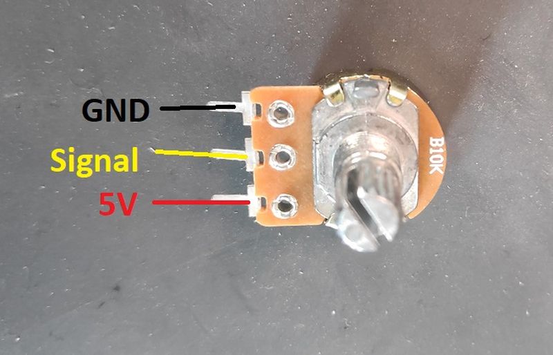
Again, if the potentiometer is the wrong way round, simply change GND and 5V.
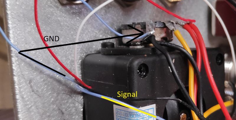
Push button with LED
With the buttons I use on the pictures you can also swap GND and 5V.
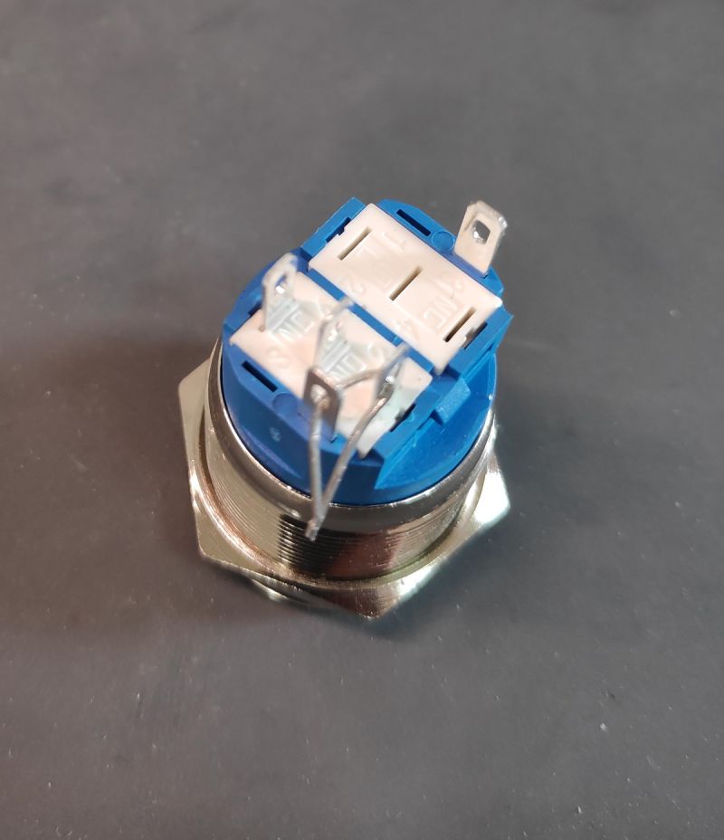
Here we can use the legs of the resistors. This makes soldering easier. The switching contact is connected with a LED contact. Both are then connected to GND on the board.
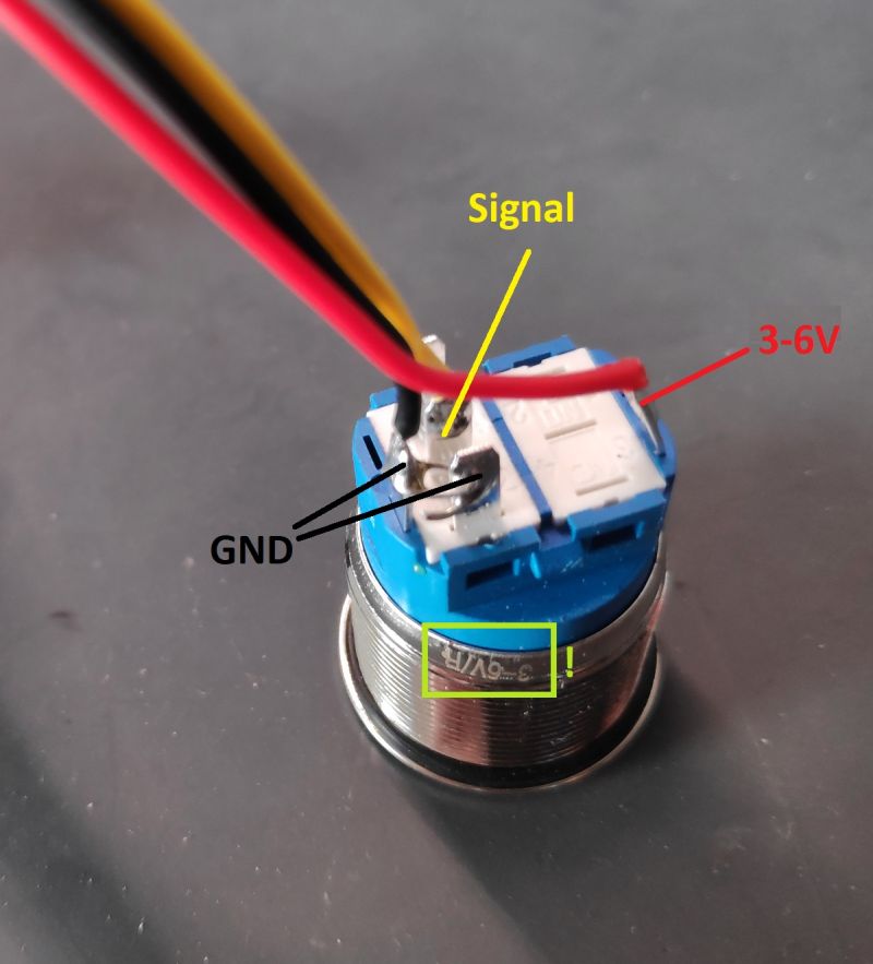
This LED of this button can work with 3-6V. Please pay attention how much Volt the LED of your button can handle. Under certain circumstances a series resistor must be installed. These are already planned on the panel boards and can be activated/deactivated by a jumper.
3-Position Switch
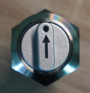
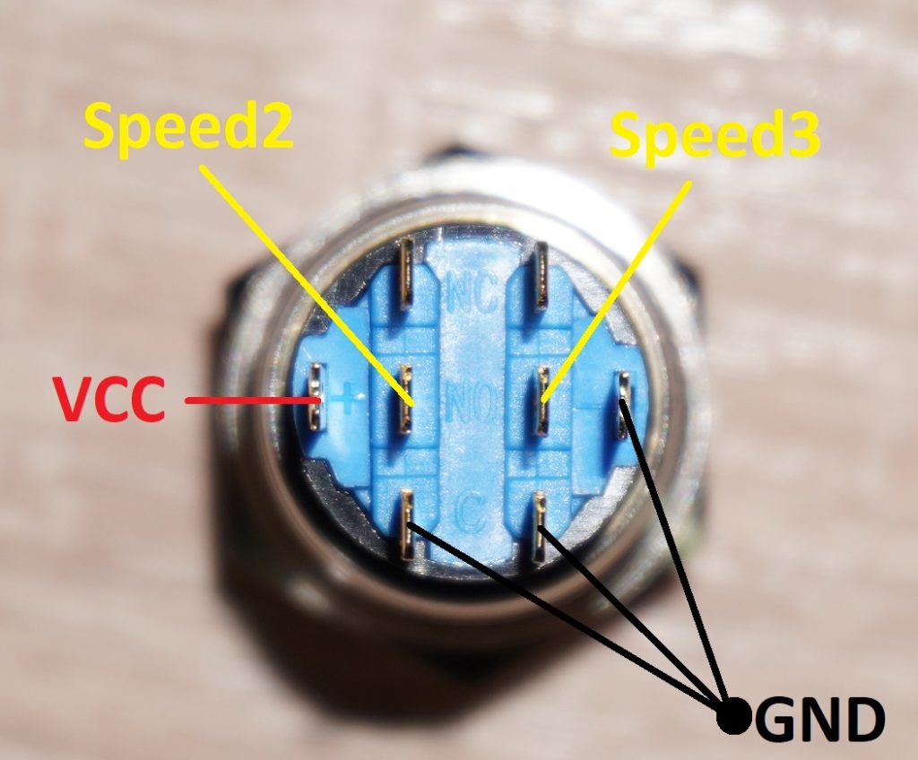
This switch is wired as shown in the picture above. In the middle position no contact is triggered. Estlcam has “Speed 1” active by default anyway, so we don’t need an extra cable for this and can leave the “Speed 1” connector free. “Speed 2” and “Speed 3” can then be connected as shown here. VCC or 5V is used for the power supply of the LED with this switch.